Table of Contents
Advertisement
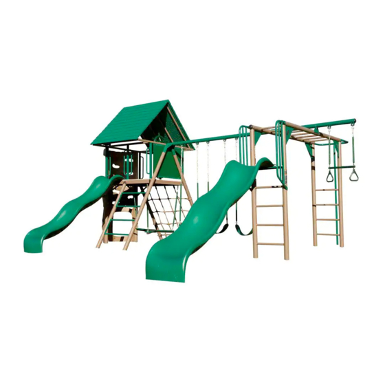
DOUBLE SLIDE
DELUXE PLAYSET
MODEL #60091
MODEL 90240
BEFORE ASSEMBLY:
• Prepare a level surface with the proper Safety Zone
(see page 12).
• 2+ people recommended for setup
Save this instruction in the event that the manufacturer has
to be contacted for replacement parts.
TOOLS REQUIRED
(1)
(1)
1/2 in/po (≈13 mm)
(1)
(2)
3/16 in/po (≈5 mm)
(2, included)
(1)
1/4 in/po (≈6 mm)
(1)
(1)
ASSEMBLY INSTRUCTIONS
(1)
5/16 in/po (≈8 mm)
(1)
(2)
TABLE OF CONTENTS
Icon Legend................................4
Warnings and Notices..................5
Safety Information.....................6
Safe Play Area..........................12
A-Frame Assembly....................13
Monkey Bar Assembly...............16
Slide Assembly..........................24
Fire Pole Assembly...................28
Deck Support Assembly.............32
Deck Assembly..........................43
Assembly................................. 50
Roof Assembly..........................56
...............................................61
Swing Assembly........................67
Maintenance Instructions..........72
Registration..............................75
Warning Sticker........................76
Warranty...................................77
MODEL# AND PRODUCT ID
(you will need both when contacting us)
Model Number: 90240
Product ID:
Advertisement
Table of Contents

Related Manuals for Lifetime 90240


Summary of Contents for Lifetime 90240
-
Page 1: Table Of Contents
Climbing Wall and Chalkboard Assembly......... 50 Roof Assembly......56 Slide and Accessories Assembly ..1/4 in/po (≈6 mm) ..........61 Swing Assembly......67 Maintenance Instructions..72 Registration......75 Warning Sticker......76 Warranty........77 MODEL# AND PRODUCT ID (you will need both when contacting us) Model Number: 90240 Product ID:... -
Page 2: Icon Legend
ICON LEGEND Indicates special heed should be taken when reading. Indicates the parts to be used for a section. Indicates no parts required for a specifi c section. Indicates the hardware to be used for a section. Indicates no hardware required for a specifi c page. Indicates the tools to be used for a section. -
Page 3: Warnings And Notices
WARNINGS & NOTICES SAFETY INSTRUCTIONS FAILURE TO FOLLOW THESE WARNINGS MAY RESULT IN SERIOUS INJURY OR PROPERTY DAMAGE AND WILL VOID WARRANTY. Owner must ensure that all players know and follow these rules for safe operation of the system. To ensure safety, do not attempt to assemble this product without following the instructions carefully. Check entire box and inside all packing material for parts and/or additional instruction material. -
Page 4: Safety Information
**IMPORTANT SAFETY INFORMATION** PLEASE READ BEFORE BEGINNING ASSEMBLY: INSTALLATION & GROUND PREPARATION INSTRUCTIONS • Place the equipment on a level, well-drained ground, not less than 6.6 ft (2.0 m) from any struc- ture or obstruction such as a fence, garage, house, overhanging branches, laundry lines, or electrical wires •... - Page 5 CONSUMER INFORMATION SHEET FOR PLAYGROUND SURFACING MATERIALS* Select Protective Surfacing—One of the most important things you can replenish and/or redistribute the surfacing. do to reduce the likelihood of serious head injuries is to install shock- absorbing protective surfacing under and around your play equipment. Do not install loose fi...
-
Page 6: Safe Play Area
SAFE PLAY AREA SAFETY ZONE — Place the equipment no less than 6.6 ft. (2.0 m) from any structure or obstruction such as a fence, garage, house, overhanging branches, laundry lines, or electrical wires. Make sure the clearance in front of and behind the swings is at least twice the height of the swing bar. The impact surfacing needs to cover the entire recommended play area. -
Page 7: A-Frame Assembly
A-FRAME ASSEMBLY HARDWARE REQUIRED Hardware Blister Pack DZR (x6) CCL (x2) BTS (x4) AAN (x6) DZQ (x6) DSA (x4) PARTS REQUIRED CONTENTS OF BOX 1 CBE (x1) CBF (x1) CONTENTS OF BOX 2 / CONTENU DE LA BOÎTE 2 CONTENIDO DE LA CAJA 2 CB0 (x1) TOOLS REQUIRED 1/2 in/po (≈13 mm) - Page 8 SECTION 1 (CONTINUED) TOOLS AND HARDWARE REQUIRED 1/2 in/po (≈13 mm) 3/16 in/po (≈5 mm) DZR (x6) AAN (x6) DZQ (x6) • Attach the Pendulums (DZQ) to the Swing Bar (CB0) using the hardware indicated. Do this for each set of brackets on the Swing Bar.
- Page 9 SECTION 1 (CONTINUED) TOOLS AND HARDWARE REQUIRED 3/16 in/po (≈5 mm) DSA (x4) BTS (x4) • Attach an A-Frame Pole (CBE) to the Swing Bar (CBO) in the location indicated. • If your A-Frame pole has a dimpled hole, make sure the dimpled hole faces away from the Swing Bar.
-
Page 10: Monkey Bar Assembly
MONKEY BAR ASSEMBLY HARDWARE REQUIRED Hardware Blister Pack DSA (x22) DZR (x2) BTS (x22) ARO (x10) AAN (x2) DZQ (x2) PARTS REQUIRED Parts Bag CSA (x4) CSD (x5) CSB (x4) - Page 11 MONKEY BAR ASSEMBLY PARTS REQUIRED CONTENTS OF BOX 4 CSC (x1) CRY (x1) CRX (x1) CWV (x4) CONTENTS OF BOX 2 CRR (x1) TOOLS REQUIRED 1/2 in/po (≈13 mm) 3/16 in/po (≈5 mm)
- Page 12 SECTION 2 (CONTINUED) TOOLS AND HARDWARE REQUIRED 3/16 in/po (≈5 mm) 1/2 in/po (≈13 mm) DZR (x2) ARO (x2) AAN (x2) DZQ (x2) • Attach the Pendulums (DZQ) to the Trapeze Swing Bar (CRR) using the hardware indicated. • Attach the End Cap (CSD) to the Trapeze Swing Bar (CRR). Secure the End Cap with two (2) Cap Plugs (ARO).
- Page 13 SECTION 2 (CONTINUED) TOOLS AND HARDWARE REQUIRED 3/16 in/po (≈5 mm) DSA (x8) BTS (x8) ARO (x8) • Attach the Round Foot Caps (CSB) to the Fire Pole Ladder (CRX) and Slide Ladder (CRY) at the locations shown. Secure the Round Foot Caps with Cap Plugs (ARO). •...
- Page 14 SECTION 2 (CONTINUED) TOOLS AND HARDWARE REQUIRED 3/16 in/po (≈5 mm) DSA (x8) BTS (x8) • Attach the Saddle Caps (CSA) to the Fire Pole Ladder (CRX) and the Slide Ladder (CRY), then attach the Ladders to the Monkey Bars (CSC) using the hardware indicated. Make sure the Saddle Caps are oriented as shown, with the Monkey Bars resting in the saddle.
- Page 15 SECTION 2 (CONTINUED) TOOLS AND HARDWARE REQUIRED • Insert the End Caps (CSD) into the openings at each end of the poles on the Monkey Bars Assembly. • Make sure the holes in each Cap line up with the holes in the tubes of the Monkey Bars.
- Page 16 SECTION 2 (CONTINUED) TOOLS AND HARDWARE REQUIRED 3/16 in/po (≈5 mm) DSA (x4) BTS (x4) • Stand the assembly on its feet. Using a ladder, attach the the Trapeze Swing Bar (CRR) to the Monkey Bars Assembly with the hardware indicated. Install the hardware nearest to the Pendulums fi rst. Pendulum •...
- Page 17 SECTION 2 (CONTINUED) TOOLS AND HARDWARE REQUIRED 3/16 in/po (≈5 mm) DSA (x2) BTS (x2) • Have one person hold the A-Frame Swing Assembly in position. Standing carefully on a ladder, attach the the A-Frame Assembly to the Monkey Bar Assembly using the hardware indicated. Tighten all hardware from this section before continuing to the next section.
-
Page 18: Slide Assembly
SLIDE ASSEMBLY HARDWARE REQUIRED Hardware Bag DSA (x4) DXY (x4) BTS (x8) ARX (x3) ARL (x6) CVZ (x4) ARM (x3) PARTS REQUIRED CONTENTS OF BOX 2 CONTENTS OF BOX 4 CRQ (x2) CRU (x1) CONTENTS OF BOX 5 LARGE PLASTIC PARTS BEK (x1) BEO (x1) TOOLS REQUIRED... - Page 19 SECTION 3 (CONTINUED) TOOLS AND HARDWARE REQUIRED 3/16 in/po (≈5 mm) DSA (x4) BTS (x4) • Attach a Slide Rail (CRQ) to the Slide Ladder in the position shown. Repeat this step for the other Slide Rail. • Do not completely tighten the hardware until instructed later in the assembly.
- Page 20 SECTION 3 (CONTINUED) TOOLS AND HARDWARE REQUIRED 3/16 in/po (≈5 mm) DXY (x4) BTS (x4) CVZ (x4) • Secure the Deck Support (CRU) to the Slide Rails using the hardware indicated. Tighten this hardware and the hardware from Sec 3.1. •...
- Page 21 SECTION 3 (CONTINUED) TOOLS AND HARDWARE REQUIRED 1/2 in/po (≈13 mm) 5/16 in/po (≈10 mm) 3/16 in/po (≈5 mm) ARX (x3) ARM (x3) ARL (x6) • Attach the Slide (BEK) to the Deck (BEO) in the location indicated with the hardware indicated. Top View Bottom View CAUTION...
-
Page 22: Fire Pole Assembly
FIRE POLE ASSEMBLY HARDWARE REQUIRED Hardware Blister Pack DXY (x1) BTS (x3) DSA (x2) PARTS REQUIRED CONTENTS OF BOX 1 CONTENTS OF BOX 2 CONTENTS OF BOX 4 24” CRZ (x1) CRS (x1) CRT (x1) TOOLS REQUIRED 3/16 in/po (≈5 mm) - Page 23 SECTION 4 (CONTINUED) TOOLS AND HARDWARE REQUIRED • Make sure the playground is in the desired location and measure 21 in diagonally from each pole of the Fire Pole Ladder (CRX) as shown, and mark the ground where the two measurements meet. Use a Hammer or Rubber Mallet to drive the Anchor Rod (CRZ) into the ground until half of the Anchor Rod is underground.
- Page 24 SECTION 4 (CONTINUED) TOOLS AND HARDWARE REQUIRED 3/16 in/po (≈5 mm) DSA (x2) BTS (x2) • Slide the plate-end of the Fire Pole (CRT) over the • Attach the Fire Pole Hoop (CRS) to the Monkey Bars Anchor Rod (CRZ). Assembly by sliding the Connecting Tube into the Fire Pole and securing the Fire Pole Hoop with the hardware indicated.
- Page 25 SECTION 4 (CONTINUED) TOOLS AND HARDWARE REQUIRED 3/16 in/po (≈5 mm) DXY (x1) BTS (x1) • Secure the Fire Pole to the Fire Pole Hoop with the hardware indicated.
-
Page 26: Deck Support Assembly
DECK SUPPORT ASSEMBLY HARDWARE REQUIRED Hardware Bag DSA (x10) BTS (x20) DXY (x10) ARU (x1) ATV (x2) ARV (x8) AAF (x8) ARL (x3) ARO (x4) Parts Bag ARY (x2) BFD (x4) CAC (x2) ASV (x2) EII (x6) PARTS REQUIRED CONTENTS OF BOX 1 CBN (x1) CBJ (x1) CBK (x1) - Page 27 DECK SUPPORT ASSEMBLY PARTS REQUIRED CONTENTS OF BOX 2 CBP (x4) CBC (x1) CBQ (x2) CBB (x1) CBD (x1) CBA (x1) CONTENTS OF BOX 3 CONTENTS OF BOX 6 CBL (x1) CBM (x1) TOOLS REQUIRED 3/16 in/po (≈5 mm)
- Page 28 SECTION 5 (CONTINUED) TOOLS AND HARDWARE REQUIRED 3/16 in/po (≈5 mm) DSA (x4) AAF (x4) DXY (x2) ASV (x2) EII (x2) BTS (x6) • Attach the Wall-side Deck Support (CBA) to the Left Vertical Pole (CBK) and Right Vertical Pole (CBJ) and secure with the hardware indicated.
- Page 29 SECTION 5 (CONTINUED) TOOLS AND HARDWARE REQUIRED DSA (x4) 3/16 in/po (≈5 mm) BTS (x6) AAF (x4) EII (x2) DXY (x2) • Attach the Deck Support Tube, Net-side (CBB) to the Left Vertical Tube (CBK) using the hardware indicated. Make sure a Cross Brace (CBP) is secured between the Support Tube and the Vertical Pole.
- Page 30 SECTION 5 (CONTINUED) TOOLS AND HARDWARE REQUIRED 3/16 in/po (≈5 mm) BTS (x6) DXY (x6) • Attach the Deck Support Tube, Swing-side (CBD) to the Deck Support Assembly using the hardware indicated. Install the Inside Deck Support (CBL) in the position indicated and secure with the hardware shown. Hook on Inside Deck Support points downward...
- Page 31 SECTION 5 (CONTINUED) TOOLS AND HARDWARE REQUIRED 3/16 in/po (≈5 mm) EII (x2) DSA (x2) BTS (x2) • Attach the Deck Support Assembly to the A-Frame Assembly using the hardware indicated. Insert a Rectangular Tube Plug (EII) in each end of the Deck Support Tube, Swing-side (CBD) once hardware is secure. Repeat this on the opposite side of the assembly to secure the Deck Support Assembly to both Poles.
- Page 32 SECTION 5 (CONTINUED) TOOLS AND HARDWARE REQUIRED 3/16 in/po (≈5 mm) ARU (x1) BFD (x2) CAC (x1) ARO (x4) ARL (x1) • Slide the Ladder Cap (CAC) onto the Angled Ladder Leg (CAZ) as pictured, then connect the Angled Ladder Leg to the Ladder-side Deck Support (CBC) with the hardware indicated.
- Page 33 SECTION 5 (CONTINUED) TOOLS AND HARDWARE REQUIRED ARV (x8) • Attach the Ladder Rungs (CBQ) to the Angled Ladder Leg (CAZ) and the Ladder-side Pole (CBF) using the hardware indicated. 3.14 • This step requires two people.
- Page 34 SECTION 5 (CONTINUED) TOOLS AND HARDWARE REQUIRED 3/16 in/po (≈5 mm) CAC (x1) • Slide the Angled Cargo Leg (CAY) into the Ladder Cap (CAC) and Left Vertical Pole (CBK). Rest the Angled Cargo Leg against the Cargo Side Deck Support in the location shown. Do not secure it at this point in the assembly. •...
-
Page 35: Parts Identifier
PARTS IDENTIFIER LARGE PLASTIC PARTS CBX (x2) BEK (x2) CONTENTS OF BOX 1 CBU (x2) CBW (x1) CBV (x1) 24” CRZ (x1) CBE (x1) CBF (x1) CBJ (x1) CBK (x1) CBN (x1) CBY (x1) CAY (x1) CAZ (x1) - Page 36 PARTS IDENTIFIER CONTENTS OF BOX 2 CB0 (x1) CBP (x4) CCG (x3) CBQ (x2) CRU (x1) CBS (x4) CBT (x2) CBA (x1) CBB (x1) CBC (x1) CCI (x1) CBD (x1) CRR (x1) CCJ (x1) CRT (x1)
- Page 37 PARTS IDENTIFIER CONTENTS OF BOX 3 CCA (x2) CBL (x1) CCB (x8) CONTENTS OF BOX 4 CSC (x1) CRQ (x2) CRX (x1) CWV (x4) CRS (x1) CRY (x1)
- Page 38 PARTS IDENTIFIER CONTENTS OF BOX 5 BEO (x1) CBZ (x1) CCC (x4) CBR (x1) CONTENTS OF BOX 6 CCD (x1) CCF (x3) CCE (x1) CCH (x3) CAA (x1) CAB (x1) BKU (x1) CBM (x1) BKT (x3) Hardware Bags and Blister Packs...
- Page 39 SECTION 5 (CONTINUED) TOOLS AND HARDWARE REQUIRED 3/16 in/po (≈5 mm) ARY (x2) • While one person holds the Angled Cargo Leg in place, straighten out the ropes of the Cargo Net (CBM) and slide the Cargo Net up the angled poles on the playset. The large loops go on the sides and the small loops go at the top and bottom.
- Page 40 SECTION 5 (CONTINUED) TOOLS AND HARDWARE REQUIRED ATV (x2) 3/16 in/po (≈5 mm) ARL (x2) BFD (x2) 5.10 • Secure the Cargo Net Bottom Pole (CBN) to the angled poles with the Bolt (ATV) going through the angled Foot Caps as shown.
-
Page 41: Deck Assembly
DECK ASSEMBLY HARDWARE REQUIRED Hardware Bag DRZ (x6) ASB (x1) DXY (x18) Parts Bag ARU (x1) BTS (x24) ARL (x1) AAF (x3) AOF (x2) Parts Bag EIF (x2) EIG (x4) - Page 42 DECK ASSEMBLY PARTS REQUIRED CONTENTS OF BOX 1 / CONTENU DE LA BOÎTE 1 CONTENIDO DE LA CAJA 1 CBV (x1) CBW (x1) CBU (x2) CONTENTS OF BOX 2 CBS (x4) CBT (x2) CONTENTS OF BOX 5 CBR (x1) TOOLS REQUIRED 3/16 in/po (≈5 mm)
- Page 43 SECTION 6 (CONTINUED) TOOLS AND HARDWARE REQUIRED 3/16 in/po (≈5 mm) DRZ (x6) BTS (x6) • Place the Deck (CBR) on the Deck Support Assembly, textured side up. WARNING Do not stand in Clubhouse until the Deck floor is completely attached. •...
- Page 44 SECTION 6 (CONTINUED) TOOLS AND HARDWARE REQUIRED 3/16 in/po (≈5 mm) ARU (x1) ARL (x1) • Secure the Angled Cargo Leg (CAY) from step 5.8 to the Cargo Side Deck Support with the hardware indicated.
- Page 45 SECTION 6 (CONTINUED) TOOLS AND HARDWARE REQUIRED 3/16 in/po (≈5 mm) EIG (x4) DXY (x8) BTS (x8) • Place the Square Plugs (EIG) into the ends of both Deck Tubes (CBU). Attach the Deck Tubes to the Hand Rails using the Hardware indicated.
- Page 46 SECTION 6 (CONTINUED) TOOLS AND HARDWARE REQUIRED 3/16 in/po (≈5 mm) ASB (x1) BTS (x4) AAF (x1) DXY (x4) • Attach the A-Frame Roof Tube (CBV) to the One-Handle Rails (CBS) and the Swing Bar (CBO) with the hardware shown in the locations indicated.
- Page 47 SECTION 6 (CONTINUED) TOOLS AND HARDWARE REQUIRED 3/16 in/po (5 mm) DXY (x6) AOF (x2) BTS (x6) EIF (x2) AAF (x2) • Secure the Climbing Wall Deck Tube (CBW) to the One-Handle Rails (CBS) with the hardware indicated. • Secure the Climbing Wall Deck Tube (CBW) to the Right Vertical Pole (CBJ) and Left Vertical Pole (CBK) with the hardware indicated.
-
Page 48: Climbing Wall And Chalkboard Assembly
CLIMBING WALL AND CHALKBOARD ASSEMBLY HARDWARE REQUIRED Hardware Bag ADW (x10) ADV (x10) Hardware Bag ASF (x2) ARV (x3) CHX (x2) PARTS REQUIRED CONTENTS OF BOX 1 CBY (x1) CONTENTS OF BOX 4 LARGE PLASTIC PARTS CBZ (x1) CBX (x2) TOOLS REQUIRED 1/4 in/po (≈7 mm) - Page 49 SECTION 7 (CONTINUED) TOOLS AND HARDWARE REQUIRED 1/4 in/po (≈7 mm) • Place a Climbing Wall Panel (CBX) on the ground, or in a safe drilling position. The indentations in the Climbing Wall indicate the locations needed to be drilled. Using a 1/4 in Drill Bit (not included), drill completely through the plastic.
- Page 50 SECTION 7 (CONTINUED) TOOLS AND HARDWARE REQUIRED ADW (x5) • Place the Climbing Wall Pole (CBY) into one of the notches on the Climbing Wall Panel (CBX) as shown. Secure the Pole to the Climbing Wall with the hardware indicated.
- Page 51 SECTION 7 (CONTINUED) TOOLS AND HARDWARE REQUIRED ADV (x5) • Place a Climbing Wall Panel (CBX) that is attached to the Climbing Wall Pole (CBY) in the location shown. Make sure the Climbing Wall Panel is oriented as shown. Secure the Climbing Wall Panel to the Left Vertical Pole (CBK) with the hardware indicated.
- Page 52 SECTION 7 (CONTINUED) TOOLS AND HARDWARE REQUIRED ADW (x5) ADV (x5) • Place the other Climbing Wall Panel (CBX) that is not attached to the Climbing Wall Pole (CBY) in the location shown. Make sure the Climbing Wall Panel is oriented as shown in the image below. Attach this Panel to the Wall Pole using the Screws (ADW) and the Right Vertical Pole (CBJ) using the Screws (ADV).
- Page 53 SECTION 7 (CONTINUED) TOOLS AND HARDWARE REQUIRED ASF (x2) ARV (x3) CHX (x2) • Place the Chalkboard (CBZ) between the Deck (CBR) and the A-Frame Deck Tube (CBV). Secure the bottom of the Chalkboard with two Screws (ASF). Attach the top of the chalkboard with the hardware indicated. Bottom of Chalkboard-complete for both sides...
-
Page 54: Roof Assembly
ROOF ASSEMBLY HARDWARE REQUIRED Hardware Bag BTS (x8) ARO (x4) DXY (x8) ASE (x4) BRL (x4) Parts Bag ADV (x48) ARN (x8) ARL (x8) EIG (x4) EIH (x8) PARTS REQUIRED CONTENTS OF BOX 3 CCA (x2) CCB (x8) CONTENTS OF BOX CCC (x4) TOOLS REQUIRED 3/16 in/po (≈5 mm) - Page 55 SECTION 8 (CONTINUED) TOOLS AND HARDWARE REQUIRED 3/16 in/po (≈5 mm) EIG (x4) ARN (x4) ARO (x4) BRL (x4) • Secure the Round Roof Tubes (CCA) to the A-Frame and Climbing Wall Deck Tubes (CBV, CBW). Secure the Round Roof Tubes with the hardware shown.
- Page 56 SECTION 8 (CONTINUED) TOOLS AND HARDWARE REQUIRED 3/16 in/po (≈5 mm) 1/2 in/po (≈13 mm) ARN (x4) BTS (x8) DXY (x8) ASE (x4) ARL (x8) • Connect two Roof Trusses (CCB) together as shown. Repeat this step three more times to connect the other six Trusses.
- Page 57 SECTION 8 (CONTINUED) TOOLS AND HARDWARE REQUIRED ADV (x24) • Attach the Roof Panels (CCC) to the Roof Trusses (CCA), and secure the panels as shown. The notch at the top of the panel will line up with the top of the Trusses. The Roof Panels placed on top need to have a notch as shown.
- Page 58 SECTION 8 (CONTINUED) TOOLS AND HARDWARE REQUIRED ADV (x24) EIH (x8) • Connect the two remaining Roof Panels (CCC) with the hardware shown. • Insert the Dome Caps (EIH) into the ends of the Roof Trusses (CCB). Tap lightly with a Rubber Mallet if necessary.
-
Page 59: Slide And Accessories Assembly
SLIDE AND ACCESSORIES ASSEMBLY HARDWARE REQUIRED Hardware Bag ARX (x3) ARM (x3) ARL (x6) Hardware Bag ARM (x1) ARU (x1) BZV (x1) DXY (x1) BTS (x1) BRL (x2) Hardware Bag ASH (x1) BZU (x2) BZT (x1) ARM (x2) BRL (x1) - Page 60 SLIDE AND ACCESSORIES ASSEMBLY PARTS REQUIRED CONTENTS OF BOX 6 CAB (x1) CCE (x1) CCD (x1) CAA (x1) LARGE PLASTIC PARTS BEK (x1) TOOLS REQUIRED 3/16 in/po (≈5 mm) 1/2 in/po (≈13 mm) 1/2 in/po (≈13 mm) 3/8 in/po (≈10 mm)
- Page 61 SECTION 9 (CONTINUED) TOOLS AND HARDWARE REQUIRED 3/8 in/po (≈10 mm) • Use the Electric Drill to drill a hole through each of the three indents at the top of the slide.
- Page 62 SECTION 9 (CONTINUED) TOOLS AND HARDWARE REQUIRED 3/16 in/po (≈5 mm) 1/2 in/po (≈13 mm) ARM (x3) ARX (x3) ARL (x6) • Attach the Slide (BEK) to the Deck (CBR) with the hardware indicated. CAUTION • Slide can get hot in direct sunlight. It is not recommended that a slide be installed facing south.
- Page 63 SECTION 9 (CONTINUED) TOOLS AND HARDWARE REQUIRED 3/16 in/po (≈5 mm) ARU (x1) 1/2 in/po (≈13 mm) BTS (x1) ARM (x1) BRL (x2) DXY (x1) • Attach the Binocular Bracket (BZV) to the Climbing Wall Deck Tube (CBW) and secure with the hardware shown. Attach the Binoculars (CCD) to the Bracket with the hardware shown.
- Page 64 SECTION 9 (CONTINUED) TOOLS AND HARDWARE REQUIRED 1/2 in/po (≈13 mm) 3/16 in/po (≈5 mm) ASH (x1) 1/2 in/po (≈13 mm) ARM (x2) BZT (x1) BRL (x1) BZU (x2) • Slide the Hex Bolt (ASH) into the center hole of the Wheel Clicker Hub (CAB) as shown. Attach the Wheel Clicker Hub to the A-Frame Deck Tube (CBV) and secure with the hardware shown.
-
Page 65: Swing Assembly
SWING ASSEMBLY HARDWARE REQUIRED Hardware Bag BZY (x6) ABK (x3) ASM (x6) ARM (x6) ARL (x3) ASL (x3) Hardware Bag EIG (x6) CUY (x1) - Page 66 SWING ASSEMBLY PARTS REQUIRED CONTENTS OF BOX 2 CCG (x3) CCI (x1) CCJ (x1) CONTENTS OF BOX 6 BKT (x3) BKU (x1) CCF (x3) CCH (x3) TOOLS REQUIRED 3/16in/po (≈5 mm) 1/2 in/po (≈13 mm)
- Page 67 SECTION 10 (CONTINUED) TOOLS AND HARDWARE REQUIRED 3/16 in/po (≈5 mm) (x2) BZY (x6) 1/2 in/po (≈13 mm) ABK (x3) (x1) ARL (x3) ASL (x3) EIG (x6) ARM (x6) CCI (x1) 10.1 • Place the Plastic Seat (CCF) on top of the Under-Deck Swing Tube (CCG) and secure with the hardware shown. After securing the seat to the tube, place the Square Plug Caps (EIG) into the end of the Tube with the Eye Bolt (ASL).
- Page 68 SECTION 10 (CONTINUED) TOOLS AND HARDWARE REQUIRED / OUTILS ET ACCESSOIRES REQUIS INSTRUMENTAL Y HERRAJE REQUERIDOS ASM (x6) 10.3 • Attach a Quick Link (ASM) to both ends of each Soft Grip Chain. Attach the Soft Grip Chains (CCH) to the Eye Bolts (ASL) in the Under-Deck Swing Assembly.
- Page 69 SECTION 10 (CONTINUED) TOOLS AND HARDWARE REQUIRED (x1) 10.5 • Attach the Belt Swings (BKT) and the Trapeze Swing (BKU) to the Swing Hardware as shown.
-
Page 70: Maintenance Instructions
MAINTENANCE INSTRUCTIONS If routine checks and maintenance procedures are not done, the equipment could overturn and/or become a hazard. At the beginning of each play season: • Tighten all hardware. • Lubricate all metallic moving parts. • Check all protective coverings on bolts, pipes, edges and corners. Replace if they are loose, cracked or missing. •... - Page 71 ADDITIONAL WARNINGS WARNING THIS PRODUCT IS INTENDED FOR THE USE BY CHILDREN • Instruct children not to use the equipment in a manner other FROM AGES 3 TO 12, AND IS FOR RESIDENTIAL USE ONLY. than intended. Do not install over concrete, asphalt, packed earth, or any •...
- Page 72 2. This warranty is nontransferable and is expressly limited to the repair or replacement of defective playground equipment. If the equipment is defective within the terms of this warranty, Lifetime Products, Inc. will repair or replace defective parts at no cost to the purchaser.
- Page 73 2. This warranty is nontransferable and is expressly limited to the repair or replacement of defective playground equipment. If the equipment is defective within the terms of this warranty, Lifetime Products, Inc. will repair or replace defective parts at no cost to the purchaser.
Need help?
Do you have a question about the 90240 and is the answer not in the manual?
Questions and answers
what is the Toque of the assembly bolts
The torque specification for the assembly bolts of the Lifetime 90240 is not provided in the given context.
This answer is automatically generated