Simple Motors Kit 8 Assembly Instructions Manual
Hide thumbs
Also See for Kit 8:
- Assembly instructions manual (10 pages) ,
- Assembly instructions manual (20 pages)
Advertisement
Quick Links
Assembly Instructions: Kit #8
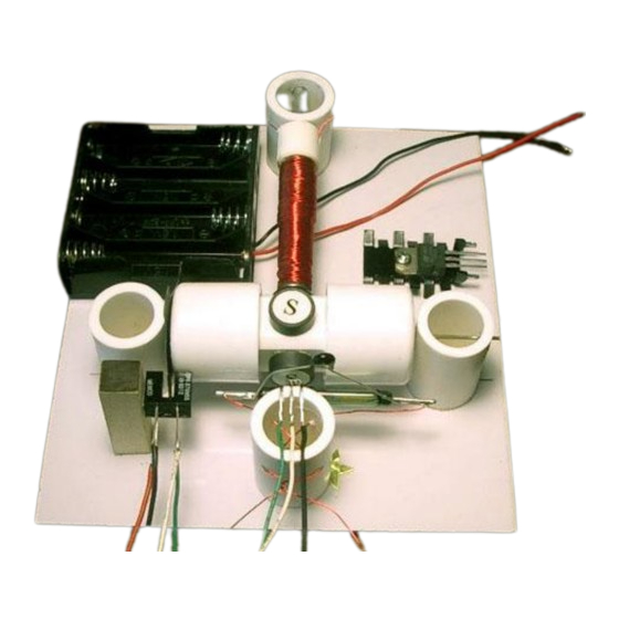
With Kit #8 you have two choices:
·
You may build each of the motors one at a time using separate assembly instructions for
each motor (this is the easier way).
-or-
·
You may assemble all parts on the board as shown in the picture above and switch between
the 4 motor circuits by re-soldering connections between parts. This option is described
below.
1. Insert the T-pin into one of the caps.
Assembly instructions for kit #8
All rights reserved. 2001 Simple Motors, LLC ♦
♦
www.simplemotor.com
1
Advertisement

Related Manuals for Simple Motors Kit 8


Summary of Contents for Simple Motors Kit 8
- Page 1 You may assemble all parts on the board as shown in the picture above and switch between the 4 motor circuits by re-soldering connections between parts. This option is described below. 1. Insert the T-pin into one of the caps. Assembly instructions for kit #8 All rights reserved. 2001 Simple Motors, LLC ♦ ♦ www.simplemotor.com...
- Page 2 The T-pin must be secured firmly. This process may require some strength. Be careful not to bend the T-pin or poke yourself. Assembly instructions for kit #8 All rights reserved. 2001 Simple Motors, LLC ♦ ♦ www.simplemotor.com...
- Page 3 Keep in mind that super glue bonds instantly, so try to be as accurate as possible in these procedures. Assembly instructions for kit #8 All rights reserved. 2001 Simple Motors, LLC ♦ ♦ www.simplemotor.com...
- Page 4 14. Otherwise, insert the nail into the stand with the green star. If it is loose you may apply glue as shown below. Assembly instructions for kit #8 All rights reserved. 2001 Simple Motors, LLC ♦ ♦ www.simplemotor.com...
- Page 5 If one or more do, move the electromagnet back until there is a 1/16" (1.5 mm) gap between the electromagnet and the closest magnet on the rotor. Assembly instructions for kit #8 All rights reserved. 2001 Simple Motors, LLC ♦ ♦ www.simplemotor.com...
- Page 6 Only solder one lead at a time and allow the device to cool before soldering the next connection. Assembly instructions for kit #8 All rights reserved. 2001 Simple Motors, LLC ♦ ♦ www.simplemotor.com...
- Page 7 18. Attach the self-sticking felt pad to the reed switch stand as shown. This soft pad decreases the reed switch vibration thus decreasing the sound it generates. Assembly instructions for kit #8 All rights reserved. 2001 Simple Motors, LLC ♦ ♦ www.simplemotor.com...
- Page 8 See the Links page at our web site for tips on soldering. Assembly instructions for kit #8 All rights reserved. 2001 Simple Motors, LLC ♦ ♦ www.simplemotor.com...
- Page 9 Hall Effect IC cool off, and then try it again. Only solder one lead at a time and allow the device to cool before soldering the next connection. 22. Bend the Hall Effect switch leads 90 degrees with branded side facing outside: Assembly instructions for kit #8 All rights reserved. 2001 Simple Motors, LLC ♦ ♦ www.simplemotor.com...
- Page 10 (1.5, 3, 4.5, and 6 V DC). You will need 4 AA size batteries. To understand how the jumper wire works let's take a look at the connections inside a typical battery holder: Assembly instructions for kit #8 All rights reserved. 2001 Simple Motors, LLC ♦ ♦ www.simplemotor.com...
- Page 11 This is how the jumper wire is actually used for 3 Volts experiments (one end is disconnected and may serve as on/off switch): Assembly instructions for kit #8 All rights reserved. 2001 Simple Motors, LLC ♦ ♦ www.simplemotor.com...
- Page 12 Make sure the batteries are fresh and connected properly. If the motor still does not work – check Troubleshooting section of our web site. This is the wiring diagram for the reed switch motor: Assembly instructions for kit #8 All rights reserved. 2001 Simple Motors, LLC ♦ ♦ www.simplemotor.com...
- Page 13 It may burn your fingers if you touch it and eventually may destroy the transistor. This is the wiring diagram for the reed switch motor with transistor: Assembly instructions for kit #8 All rights reserved. 2001 Simple Motors, LLC ♦ ♦ www.simplemotor.com...
- Page 14 It may burn your fingers if you touch it and eventually may destroy the transistor. This is the wiring diagram for the motor on a Hall Effect switch: Assembly instructions for kit #8 All rights reserved. 2001 Simple Motors, LLC ♦ ♦ www.simplemotor.com...
- Page 15 CAUTION: Do not leave the motor connected to the batteries if the rotor is stalled. High current through the transistor will make it very hot. It may burn your fingers if you touch it and eventually may destroy the transistor. Assembly instructions for kit #8 All rights reserved. 2001 Simple Motors, LLC ♦ ♦ www.simplemotor.com...
- Page 16 This is the wiring diagram for the motor with an optical control: Assembly instructions for kit #8 All rights reserved. 2001 Simple Motors, LLC ♦ ♦ www.simplemotor.com...
Need help?
Do you have a question about the Kit 8 and is the answer not in the manual?
Questions and answers