
Related Manuals for Artel FiberLink 3390 Series


Summary of Contents for Artel FiberLink 3390 Series
- Page 1 MANUAL FiberLink 3390 Series One-Way 3G/HD/SD-SDI Transmission with two way audio, data, 10/100 Ethernet & contact closure over one or two fibers Installation and Operations Manual WWW.ARTEL.COM...
-
Page 2: Table Of Contents
Fiberlink 3390 Series Transmitter Specifications . . . . . . . . . . . . . . . . . . - Page 3 FiberLink 3390 Series Welcome Thank you for purchasing Artel Video Systems’ FiberLink 3390 Series . The 3390 Series is used to transmit or receive 3G/HD/SD-SDI with two-way audio, 10/100 Ethernet, serial data, and contact closure over one or two fibers . The Fiberlink 3390 series is compatible with single mode or multimode fiber .
-
Page 4: Model Part Number Specification
1 Channel, Bi-Directional Data Bandwidth DC to 115 Kb/sec, max . Control Format Switch selectable RS-232, RS-422 & RS-485 (4 wire or 2 wire) Protocols NRZ, NRZI, RZ, Manchester, Bi-phase Signal Connector Removable terminal block Page 4 FiberLink 3390 Series User’s Manual... -
Page 5: Audio Specifications
Output Impedance 50 Ohms nominal Audio to Video Diff . Delay (skew) <300 usec Ethernet Specifications Port 10/100 Base-T, Configured as MDI Speed 10 Mbps & 100 Mbps Ethernet, Switch Selectable Ethernet Connector RJ-45 FiberLink 3390 Series User’s Manual Page 5... -
Page 6: Contact Closure Specifications
115 Volts AC; 50/60 Hz @ 0 .2 A or 24 Volts DC @ 1 A Contact Closure Connectors Removeable terminal block Fiberlink 3390 Series Transmitter Specifications Serial Video BNC Input Specifications Number of Inputs Data Bandwidth 19 .4 Mbps to 2 .97 Gbps... -
Page 7: Fiberlink 3391 Series Receiver Specifications
LC or ST Wavelength 1100 - 1620 nm Minimum Input Sensitivity -17 dBm at 2 .97 Gbps; -19 dBm at 1 .485 Gbps -19 dBm at 270 Mbps; Maximum Input Power 0 dBm FiberLink 3390 Series User’s Manual Page 7... -
Page 8: Operating Loss Budget
*Distance specifications are approximate, based upon connecting a 3390 Transmitter to a 3391 Receiver, and are not guaranteed . Artel cannot estimate or guarantee operating loss budgets when the 3390 Series is used with other, non-Fiberlink devices . Operating loss budget must not be exceeded... -
Page 9: Installation Instructions (Cont.)
Direct viewing of this radiation should be avoided at all times! FiberLink 3390 Series User’s Manual Page 9... -
Page 10: Audio Wiring - Inputs
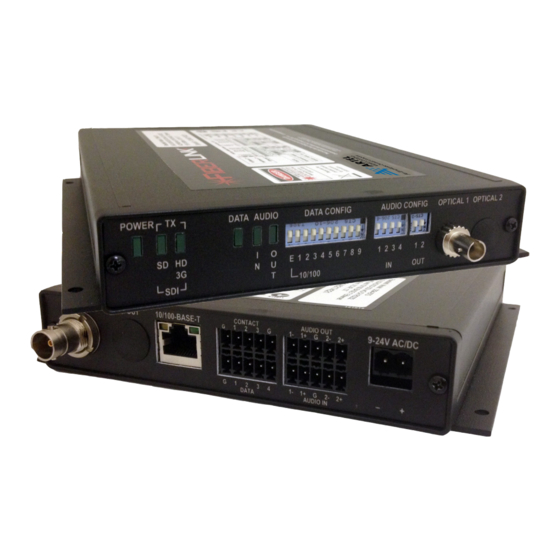
Channel 1 Ground (-) Channel 1 Output (+) Channel 1 Signal (+) Ground (Shield) Shield Channel 2 Ground (-) Channel 2 Output (-) Channel 2 Signal (+) Channel 2 Output (+) Reference Photos - Box Front/Rear Page 10 FiberLink 3390 Series User’s Manual... -
Page 11: Audio Input Switch Settings For Box Versions
Switch 1) Data Configuration For Box Versions The Fiberlink 3390 Series box units have three switch blocks; one 10 position, one 4 posi- tion, and one 2 position . The first block, “Data Config”, represents the Ethernet and RS Channel configurations . -
Page 12: Ethernet Configurations For Box Versions
E 1 2 3 4 5 6 7 8 9 E 1 2 3 4 5 6 7 8 9 DATA CONFIG 76.8k E 1 2 3 4 5 6 7 8 9 Page 12 FiberLink 3390 Series User’s Manual... -
Page 13: Data Wiring For Box Versions
+ – RS-485 - 2 Wire Input/ Output G 1 2 3 4 + – Contact Closure Wiring For Box Versions G 1 2 3 G G 1 2 3 G Input Output – FiberLink 3390 Series User’s Manual Page 13... -
Page 14: Reference Photos - Card
1 2 3 4 1 2 3 4 1 2 3 4 Switches 1 & 2) Channel 2 controlled by 1 2 3 4 1 2 3 4 1 2 3 4 Switches 3 & 4) Page 14 FiberLink 3390 Series User’s Manual... -
Page 15: Audio Output Switch Settings For Card Version
Switch 2) Data Configuration For Card Version The Fiberlink 3390 Series card units have three switch blocks; one 10 position, one 4 posi- tion, and one 2 position . The first block, “Data Config”, represents the Ethernet and RS Channel configurations . -
Page 16: Data Baud Rate Configuration For Card Versions
1 2 3 4 5 6 7 8 9 10 1 2 3 4 5 6 7 8 9 10 RS-232 RS-422/485 - 4 Wire DATA CONFIG 1 2 3 4 5 6 7 8 9 10 RS-485 - 2 Wire Page 16 FiberLink 3390 Series User’s Manual... -
Page 17: Ethernet Configurations For Card Version
+ – RS-485 - 2 Wire Input/ Output G 1 2 3 4 + – Contact Closure Wiring For Card Versions G 1 2 3 G G 1 2 3 G Input Output – FiberLink 3390 Series User’s Manual Page 17... -
Page 18: Alarm Switch Settings & Options
Down Loss of “Optical 1” Enabled Disabled for 1 Fiber Version Loss of “Optical 2” Enabled Disabled for 2 Fiber Version Loss of Receive Video Enabled Disabled Loss of Transmit Video Enabled Disabled Page 18 FiberLink 3390 Series User’s Manual... -
Page 19: Indicator Leds
Indicator LEDs FiberLink 3390 Series Indicator LEDs The FiberLink 3390 Series has several indicator LEDs that are used to monitor the state of the unit . Card versions have an additional Alarm LED . 3390, 3391, 3392, 3393 LED Definitions... -
Page 20: Operating Pointers
Customer Service Department for further assistance . If you suspect your problem is caused by the optics or the fiber optic cable, and you have an optical power meter, please take the appropriate measurements prior to contacting support . Page 20 FiberLink 3390 Series User’s Manual... -
Page 21: Maintenance And Repairs
FiberLink 3390 Series Maintenance and Repairs The FiberLink 3390 Series has been manufactured using the latest semiconductor devices and techniques that electronic technology has to offer . They have been designed for long, reliable and trouble-free service and are not normally field repairable . -
Page 22: Accessories And Related Products
± 2 .5 meters . Generates a pulsed signal for use with fiber identifiers . Easy-to- read bright red 7-segment LED display . Comes equipped with industry preferred ST connectors . Page 22 FiberLink 3390 Series User’s Manual... - Page 23 FiberLink 3390 Series FiberLink 3390 Series User’s Manual Page 23...
- Page 24 • Multimode and single mode versions • Designed and manufactured in the USA • Training and installation support available • 24x7x365 technical support available Artel Video Systems Corp. 5B Lyberty Way, Westford, MA 01886 USA T: 978-263-5775 All specifications subject to F: 978-263-9755 change without notice.
Need help?
Do you have a question about the FiberLink 3390 Series and is the answer not in the manual?
Questions and answers