Table of Contents
Advertisement
Quick Links
Advertisement
Table of Contents

Related Manuals for Asus ROG STRIX X370-I


Summary of Contents for Asus ROG STRIX X370-I
- Page 1 ROG STRIX X370-I GAMING...
- Page 2 Product warranty or service will not be extended if: (1) the product is repaired, modified or altered, unless such repair, modification of alteration is authorized in writing by ASUS; or (2) the serial number of the product is defaced or missing.
-
Page 3: Table Of Contents
Contents Safety information ....................... v About this guide ......................vi ROG STRIX X370-I GAMING specifications summary .......... viii Package contents ....................... xi Installation tools and components ................xii Chapter 1: Product Introduction Motherboard overview ................1-1 1.1.1 Before you proceed ..............1-1 1.1.2... - Page 4 3.6.8 USB Configuration ..............3-16 Monitor menu ................... 3-17 Boot menu ....................3-17 Tool menu ....................3-19 3.9.1 ASUS EZ Flash 3 Utility ............3-19 3.9.2 Secure Erase ................3-19 3.9.3 ASUS Overclocking Profile ............3-20 3.9.4 ASUS SPD Information ............. 3-20 3.9.5...
-
Page 5: Safety Information
Safety information Electrical safety • To prevent electrical shock hazard, disconnect the power cable from the electrical outlet before relocating the system. • When adding or removing devices to or from the system, ensure that the power cables for the devices are unplugged before the signal cables are connected. If possible, disconnect all power cables from the existing system before you add a device. -
Page 6: About This Guide
Refer to the following sources for additional information and for product and software updates. ASUS website The ASUS website (www.asus.com) provides updated information on ASUS hardware and software products. Optional documentation Your product package may include optional documentation, such as warranty flyers, that may have been added by your dealer. - Page 7 Conventions used in this guide To ensure that you perform certain tasks properly, take note of the following symbols used throughout this manual. DANGER/WARNING: Information to prevent injury to yourself when trying to complete a task. CAUTION: Information to prevent damage to the components when trying to complete a task.
-
Page 8: Rog Strix X370-I Gaming Specifications Summary
ROG STRIX X370-I GAMING specifications summary AMD AM4 socket for AMD Ryzen™ / 7th Generation A-series / Athlon™ Processors Supports AMD AM4 Socket 14nm CPU * Refer to www.asus.com for CPU support list. Chipset AMD X370 AMD Ryzen™ Processors - 2 x DIMM, max. 32GB, DDR4 3600(O.C.) / 3400(O.C.) / 3333(O.C.)/ 3200(O.C.) / 3000(O.C.) / 2800(O.C.) / 2666 / 2400 / 2133 MHz, ECC and non-ECC, un-... - Page 9 ROG STRIX X370-I GAMING specifications summary AMD Ryzen™ / 7th Generation A-series / Athlon™ Processors - 4 x USB 3.1 Gen 1 ports (4 ports at back panel [blue]) AMD X370 chipset - 2 x USB 3.1 Gen 2 ports (2 ports at back panel [red], Type-A) - 2 x USB 3.1 Gen 1 ports (2 ports at mid-board)
- Page 10 1 x Anti-surge LAN (RJ-45) port Back I/O Ports 1 x ASUS Wi-Fi module (Wi-Fi 802.11 a/b/g/n/ac and Bluetooth v4.2) 3 x LED-illuminated audio jacks* * Use a chassis with HD audio module in the front panel to support an 8-channel audio output.
-
Page 11: Package Contents
ROG STRIX X370-I GAMING 4 x SATA 6 Gb/s cables Cables 1 x Addressable LED extension cable 1 x Panel cable 1 x ASUS 2T2R dual band Wi-Fi moving antennas (Wi-Fi 802.11a/b/g/n/ac compliant) 1 x I/O Shield 1 x ROG Strix sticker Accessories 1 x M.2 mounting kit... -
Page 12: Installation Tools And Components
Installation tools and components 1 Bag of screws Phillips (cross) screwdriver PC chassis Power supply unit AMD AM4 CPU AMD AM4 compatible CPU Fan DDR4 DIMM SATA hard disk drive SATA optical disc drive (optional) Graphics card (optional) The tools and components in the table above are not included in the motherboard package. -
Page 13: Chapter 1: Product Introduction
Chapter 1: Product Introduction Product Introduction Motherboard overview 1.1.1 Before you proceed Take note of the following precautions before you install motherboard components or change any motherboard settings. • Unplug the power cord from the wall socket before touching any component. • Before handling components, use a grounded wrist strap or touch a safely grounded object or a metal object, such as the power supply case, to avoid damaging them due to static electricity. • Hold components by the edges to avoid touching the ICs on them. • Whenever you uninstall any component, place it on a grounded antistatic pad or in the bag that came with the component. • Before you install or remove any component, ensure that the ATX power supply is switched off or the power cord is detached from the power supply. Failure to do so may cause severe damage to the motherboard, peripherals, or components. ROG STRIX X370-I GAMING... -
Page 14: Motherboard Layout
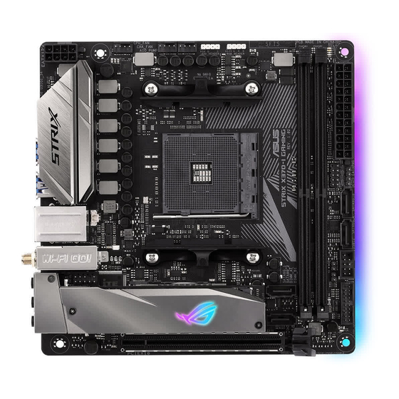
1.1.2 Motherboard layout 17.0cm(6.7in) BOOT ADD_HEADER RGB_HEADER DRAM CPU_FAN AIO_PUMP CHA_FAN EATX12V DIGI +EPU U31G1_34 U31G1_56 LAN_U31G2_12 AURA BATT_CON M.2(WIFI) 128Mb PCIE SATA BIOS X370 LINE_IN AAFP Super ALED1 ALED2 LINE_OUT SATA6G_1 2242 PCH_LED1 PCH_LED4 1220A 2280 2260 MIC_IN PCH_LED2 PCH_LED3 SB_PWR SATA6G_2... - Page 15 1-12 RGB header (4-pin RGB_HEADER) 1-15 AMD AM4 CPU socket DDR4 DIMM slots Q-LEDs (BOOT, VGA, DRAM, CPU) Speaker connector (4-pin SPEAKER) 1-13 System panel connector (10-1 pin F_PANEL) 1-13 10. AMD Serial ATA 6.0 Gb/s connectors (7-pin SATA6G_1-4) 1-10 11. Thermal sensor connector (2-pin T_SENSOR) 1-12 12. USB 2.0 connector (10-1 pin USB12) 1-10 13. USB 3.1 Gen 1 connector (20-1 pin U31G1_12) 1-11 14. Standby power LED (SB_PWR) 15. Clear RTC RAM jumper (2-pin CLRTC) 16. M.2 Socket 3 1-14 17. Front panel audio connector (10-1 pin AAFP) 1-11 18. RTC Battery header (2-pin BATT_CON) 19. RGB LED ROG STRIX X370-I GAMING...
-
Page 16: Central Processing Unit (Cpu)
1.1.3 Central Processing Unit (CPU) The motherboard comes with an AM4 socket designed for AMD Ryzen™ / 7th Generation A-series / Athlon™ processors up to 8-core. ROG STRIX X370-I GAMING CPU socket AM4 The AM4 socket has a different pinout design. Ensure that you use a CPU designed for the AM4 socket. The CPU fits in only one correct orientation. DO NOT force the CPU into the socket to prevent bending the connectors on the socket and damaging the CPU! Ensure that all power cables are unplugged before installing the CPU. 1.1.4 System memory The motherboard comes with two Double Data Rate 4 (DDR4) Dual Inline Memory Modules (DIMM) slots. A DDR4 module is notched differently from a DDR, DDR2, or DDR3 module. DO NOT install a DDR, DDR2, or DDR3 memory module to the DDR4 slot. ROG STRIX X370-I GAMING 288-pin DDR4 DIMM sockets Chapter 1: Product Introduction... - Page 17 Recommended memory configurations Memory configurations You may install 2 GB, 4 GB, 8 GB, and 16 GB DDR4 DIMMs into the DIMM sockets. • AMD Ryzen™ processors support ECC and non-ECC un-buffered memory. • AMD 7th Gen A-series / Athlon™ processors support non-ECC un-buffered memory. • You may install varying memory sizes in Channel A and Channel B. The system maps the total size of the lower-sized channel for the dual-channel configuration. Any excess memory from the higher-sized channel is then mapped for single-channel operation. • This motherboard does not support DIMMs made up of 512 Mb (64 MB) chips or less (Memory chip capacity counts in Megabit, 8 Megabit/Mb = 1 Megabyte/MB). • The default memory operation frequency is dependent on its Serial Presence Detect (SPD), which is the standard way of accessing information from a memory module. Under the default state, some memory modules for overclocking may operate at a lower frequency than the vendor-marked value. • For system stability, use a more efficient memory cooling system to support a full memory load (2 DIMMs) or overclocking condition. • Always install the DIMMS with the same CAS Latency. For an optimum compatibility, we recommend that you install memory modules of the same version or data code (D/C) from the same vendor. Check with the vendor to get the correct memory modules. • Visit the ASUS website for the latest QVL. ROG STRIX X370-I GAMING...
-
Page 18: Expansion Slots
1.1.5 Expansion slots Unplug the power cord before adding or removing expansion cards. Failure to do so may cause you physical injury and damage motherboard components. Slot No. Slot Description PCIe 3.0 x16 slot 1.1.6 Onboard LEDs Standby Power LED (SB_PWR) The motherboard comes with a standby power LED. The LED lights up to indicate that the system is ON, in sleep mode, or in soft-off mode. This is a reminder that you should shut down the system and unplug the power cable before removing or plugging in any motherboard component. The illustration below shows the location of the onboard LED. SB_PWR Standby Power Powered Off ROG STRIX X370-I GAMING Standby power LED Chapter 1: Product Introduction... - Page 19 ROG STRIX X370-I GAMING CPU/DRAM/ BOOT_DEVICE/VGA LED The order which the LEDs light up may vary per CPU. The Q-LEDs provide the most probable cause of an error code as a starting point for troubleshooting. The actual cause may vary from case to case. RGB LED The RGB LED lighting control provides several lighting schemes, which allow you to customize your favorite LED effect. You can set your favorite LED effect to cast a stunning multi-color glow across your build, change shades to indicate CPU temperature, pulsate in time to the beat of your music, or set your favorite color for each pair of LEDs. RGB1 RGB2 RGB3 RGB4 RGB5 RGB6 RGB LED(Bottom) RGB7 RGB8 RGB9 RGB10 RGB11 RGB12 ROG STRIX X370-I GAMING RGB LED Lighting ROG STRIX X370-I GAMING...
-
Page 20: Headers
1.1.7 Headers Clear RTC RAM jumper (2-pin CLRTC) This jumper allows you to clear the CMOS RTC RAM data of the system setup information such as date, time, and system passwords. CLRTC +3V_BAT PIN 1 ROG STRIX X370-I GAMING Clear RTC RAM To erase the RTC RAM: Turn OFF the computer and unplug the power cord. Use a metal object such as a screwdriver to short the two pins. Plug the power cord and turn ON the computer. Hold down the <Del> key during the boot process and enter BIOS setup to re-enter data. Except when clearing the RTC RAM, never place a metal object or jumper cap on the CLRTC jumper. Placing a metal object or jumper cap will cause system boot failure! • If the steps above do not help, remove the onboard battery and place a metal object or jumper cap again to clear the CMOS RTC RAM data. After the CMOS clearance, reinstall the battery. • You do not need to clear the RTC when the system hangs due to overclocking. For system failure due to overclocking, use the C.P.R. (CPU Parameter Recall) feature. Shut down and reboot the system so the BIOS can automatically reset parameter settings to default values. • Due to the chipset behavior, AC power off is required to enable C.P.R. function. You must turn off and turn on the power supply or unplug and plug the power cord before rebooting the system. -
Page 21: Internal Connectors
+5 Volts Power OK -5 Volts PIN 1 +5 Volts +5 Volts PSON# +3 Volts -12 Volts +3 Volts +3 Volts PIN 1 ROG STRIX X370-I GAMING ATX power connectors • For a fully configured system, we recommend that you use a power supply unit (PSU) that complies with ATX 12 V Specification 2.0 (or later version) and provides a minimum power of 350 W. • Do not forget to connect the 8-pin EATX12 V power plug. Otherwise, the system will not boot. • We recommend that you use a PSU with a higher power output when configuring a system with more power-consuming devices. The system may become unstable or may not boot up if the power is inadequate. - Page 22 [RAID]. • Before creating a RAID set, refer to section RAID configurations or the manual bundled in the motherboard support DVD. • When using NCQ, set the SATA Mode in the BIOS to [AHCI]. Refer to section SATA Configuration for details. USB 2.0 connector (10-1 pin USB12) This connector is for a USB 2.0 port. Connect the USB module cable to this connector, then install the module to a slot opening at the back of the system chassis. This USB connector complies with USB 2.0 specification that supports up to 480 Mb/s connection speed. USB12 USB_P2+ USB_P1+ USB_P2- USB_P1- USB+5V USB+5V PIN 1 ROG STRIX X370-I GAMING USB2.0 connector Never connect a 1394 cable to the USB connectors. Doing so will damage the motherboard! Chapter 1: Product Introduction 1-10...
- Page 23 IntA_P2_SSRX- IntA_P1_SSRX+ IntA_P2_SSRX+ IntA_P1_SSTX- IntA_P2_SSTX- IntA_P1_SSTX+ IntA_P2_SSTX+ IntA_P1_D- IntA_P2_D- IntA_P1_D+ IntA_P2_D+ ROG STRIX X370-I GAMING USB3.1 Gen1 connector The USB 3.1 Gen 1 module is purchased separately. The plugged USB 3.1 Gen 1 device may run on xHCI or EHCI mode depending on the operating system’s setting. Front panel audio connector (10-1 pin AAFP) This connector is for a chassis-mounted front panel audio I/O module that supports HD Audio. Connect one end of the front panel audio I/O module cable to this connector. AAFP PIN 1 HD-audio-compliant pin definition ROG STRIX X370-I GAMING Front panel connector We recommend that you connect a high-definition front panel audio module to this connector to avail of the motherboard’s high-definition audio capability.
- Page 24 ROG STRIX X370-I GAMING ADD header The addressable RGB header supports WS2812B addressable RGB LED strips (5V/Data/ Ground), with a maximum power rating of 3A (5V) and a maximum of 60 LEDs. Before you install or remove any component, ensure that the ATX power supply is switched off or the power cord is detached from the power supply. Failure to do so may cause severe damage to the motherboard, peripherals, or components. • Actual lighting and color will vary with LED strip. • If your LED strip does not light up, check if the addressable RGB LED strip is connected in the correct orientation, and the 5V connector is aligned with the 5V header on the motherboard. • The addressable RGB LED strip will only light up under the operating system. • The addressable RGB LED strip is purchased separately. Thermal sensor connector (2-pin T_SENSOR) This connector is for the thermistor cable that allows you to monitor the temperature of your motherboard’s critical components and connected devices. T_SENSOR SENSOR IN PIN 1 ROG STRIX X370-I GAMING Thermal sensor connector Chapter 1: Product Introduction 1-12...
- Page 25 System panel connector (10-1 pin F_PANEL) This connector supports several chassis-mounted functions. F_PANEL (NC) HWRST# Ground PWR_LED- HDD_LED- HDD_LED+ PWR_LED+ PIN 1 ROG STRIX X370-I GAMING System panel connector • System power LED (2-pin PWR_LED) This 2-pin connector is for the system power LED. Connect the chassis power LED cable to this connector. The system power LED lights up when you turn on the system power, and blinks when the system is in sleep mode. • Hard disk drive activity LED (2-pin HDD_LED) This 2-pin connector is for the HDD Activity LED. Connect the HDD Activity LED cable to this connector. The HDD LED lights up or flashes when data is read from or written to the HDD.
- Page 26 CPU and chassis fan connectors; AIO pump connector (4-pin CPU_FAN; 4-pin CHA_FAN; 4-pin AIO_PUMP) Connect the fan cables to the fan connectors on the motherboard, ensuring that the black wire of each cable matches the ground pin of the connector. CPU_FAN AIO_PUMP CHA_FAN ROG STRIX X370-I GAMING Fan connectors • DO NOT forget to connect the fan cables to the fan connectors. Insufficient air flow inside the system may damage the motherboard components. These are not jumpers! Do not place jumper caps on the fan connectors! • Ensure to fully insert the 4-pin CPU fan cable to the CPU fan connector. • The CPU_FAN connector supports the CPU fan of maximum 1A (12 W) fan power. • Connect the pump cable from the all-in-one cooler (AIO cooler) to the AIO_PUMP connector, and connect the fan cable to the CPU_FAN connector. M.2 sockets (M.2_1~2) These sockets allow you to install M.2 SSD modules.
- Page 27 RGB header (4-pin RGB_HEADER) These connector is for RGB LED strips. RGB_HEADER PIN 1 +12V G R B ROG STRIX X370-I GAMING RGB header The RGB header supports 5050 RGB multi-color LED strips (12V/G/R/B), with a maximum power rating of 3A (12V), and no longer than 3 m. Before you install or remove any component, ensure that the ATX power supply is switched off or the power cord is detached from the power supply. Failure to do so may cause severe damage to the motherboard, peripherals, or components. • Actual lighting and color will vary with LED strip. • If your LED strip does not light up, check if the RGB LED extension cable and the RGB LED strip is connected in the correct orientation, and the 12V connector is aligned with the 12V header on the motherboard. • The LED strip will only light up when the system is operating. • The LED strip is purchased separately. ROG STRIX X370-I GAMING 1-15...
- Page 28 Chapter 1: Product Introduction 1-16...
-
Page 29: Chapter 2: Basic Installation
2.1.1 Motherboard installation Install the ASUS I/O Shield to the chassis rear I/O panel. Place the motherboard into the chassis, ensuring that its rear I/O ports are aligned to the chassis’ rear I/O panel. - Page 30 Place four screws into the holes indicated by circles to secure the motherboard to the chassis. DO NOT overtighten the screws! Doing so can damage the motherboard. Chapter 2: Basic Installation...
-
Page 31: Cpu Installation
The AMD AM4 socket is compatible with AMD AM4 processors. Ensure you use a CPU designed for the AM4 socket. The CPU fits in only one correct orientation. DO NOT force the CPU into the socket to prevent bending the connectors on the socket and damaging the CPU! ROG STRIX X370-I GAMING... -
Page 32: Cooling System Installation
2.1.3 Cooling system installation Apply the Thermal Interface Material to the CPU cooling system and CPU before you install the cooling system and fan if necessary. Type 1 Chapter 2: Basic Installation... - Page 33 Type 2 When using this type of CPU fan, remove the screws and the retention module only. Do not remove the plate on the bottom. ROG STRIX X370-I GAMING...
- Page 34 To install an AIO cooler AIO_PUMP CPU_FAN CPU_OPT The illustrations in this section are for reference only. Please refer to section 1.1.2 Motherboard Layout for the actual location of the header(s). Chapter 2: Basic Installation...
-
Page 35: Dimm Installation
2.1.4 DIMM installation To remove a DIMM ROG STRIX X370-I GAMING... -
Page 36: Atx Power Connection
2.1.5 ATX power connection Ensure to connect the 8-pin power plug. 2.1.6 SATA device connection Chapter 2: Basic Installation... -
Page 37: Front I/O Connector
To install front panel audio connector To install the front panel connector AAFP To install USB 3.1 Gen 1 connector To install USB 2.0 connector USB 3.1 Gen 1 USB 2.0 2.1.8 Expansion card installation To install PCIe x16 cards ROG STRIX X370-I GAMING... -
Page 38: Installation
2.1.9 M.2 installation M.2_1 Socket (Top side) When you remove or replace the heatsink, please be careful not to bend or damage the pins on the LED connector. Install the M.2 standoff to the mounting hole fit for your M.2 card. Chapter 2: Basic Installation 2-10... - Page 39 M.2_2 Socket (Bottom side) Supported M.2 type varies per motherboard. ROG STRIX X370-I GAMING 2-11...
-
Page 40: Wi-Fi Antenna Installation
2.1.10 Wi-Fi antenna installation Installing the ASUS 2T2R dual band W-Fi antennas Connect the bundled ASUS 2T2R dual band Wi-Fi antennas to the Wi-Fi ports at the back of the chassis. • Ensure that the ASUS 2T2R dual band Wi-Fi antennas are securely installed to the Wi-Fi ports. -
Page 41: Motherboard Rear And Audio Connections
Rear Speaker Out panel) Lime (Rear panel) Line Out Front Speaker Out Front Speaker Out Front Speaker Out Pink (Rear panel) Mic In Mic In Bass/Center Bass/Center Lime (Front panel) – – – Side Speaker Out ROG STRIX X370-I GAMING 2-13... -
Page 42: Audio I/O Connections
2.2.2 Audio I/O connections Audio I/O ports Line Out Line In Mic In Connect to Headphone and Mic Connect to Stereo Speakers Connect to 2 Speakers Chapter 2: Basic Installation 2-14... - Page 43 Connect to 4 Speakers Connect to 6 Speakers Connect to 8 Speakers ROG STRIX X370-I GAMING 2-15...
-
Page 44: Starting Up For The First Time
Starting up for the first time After making all the connections, replace the system case cover. Ensure that all switches are off. Connect the power cord to the power connector at the back of the system chassis. Connect the power cord to a power outlet that is equipped with a surge protector. Turn on the devices in the following order: Monitor External SCSI devices (starting with the last device on the chain) - Page 45 ROG STRIX X370-I GAMING 2-17...
-
Page 46: Chapter 3: Bios Setup
BIOS Setup Knowing BIOS The new ASUS UEFI BIOS is a Unified Extensible Interface that complies with UEFI architecture, offering a user-friendly interface that goes beyond the traditional keyboard- only BIOS controls to enable a more flexible and convenient mouse input. You can easily navigate the new UEFI BIOS with the same smoothness as your operating system. -
Page 47: Bios Setup Program
RTC RAM via the Clear CMOS button. • The BIOS setup program does not support the Bluetooth devices. Please visit ASUS website for the detailed BIOS content manual. BIOS menu screen The BIOS Setup program can be used under two modes: EZ Mode and Advanced Mode. -
Page 48: Advanced Mode
Language MyFavorite(F3) Qfan Control(F6) EZ Tuning Wizard(F11) Go back to EZ Mode Submenu items General help Configuration fields Pop-up Menu Search on the FAQ Last modified settings Displays the CPU temperature, CPU, and memory voltage output ROG STRIX X370-I GAMING... - Page 49 Menu bar The menu bar on top of the screen has the following main items: My Favorites For saving the frequently-used system settings and configuration. Main For changing the basic system configuration Ai Tweaker For changing the overclocking settings Advanced For changing the advanced system settings For displaying the system temperature, power status, and changing Monitor...
- Page 50 Move your mouse over this button to show a QR code, scan this QR code on your mobile device to connect to the BIOS FAQ web page of the ASUS support website. You can also scan the following QR code: Hot keys This button above the menu bar contains the navigation keys for the BIOS setup program.
-
Page 51: Ez Mode
3.2.2 EZ Mode The EZ Mode provides you an overview of the basic system information, and allows you to select the display language, system performance, mode and boot device priority. To switch from Advanced Mode to EZ Mode, click EZ Mode(F7) or press the <F7> hotkey. Displays the system properties of the selected mode. -
Page 52: Q-Fan Control
Click to activate DC Mode configured PWM Mode Select a profile to Click to apply the fan setting apply to your fans Click to undo the Click to go back to main menu changes Select to manually configure your fans ROG STRIX X370-I GAMING... - Page 53 Configuring fans manually Select Manual from the list of profiles to manually configure your fans’ operating speed. Speed points Select to manually configure your fans To configure your fans: Select the fan that you want to configure and to view its current status. Click and drag the speed points to adjust the fans’...
-
Page 54: Ez Tuning Wizard
To start OC Tuning: Press <F11> on your keyboard or click from the BIOS screen to open EZ Tuning Wizard screen. Click OC then click Next. Select a PC scenario Daily Computing or Gaming/Media Editing, then click Next. ROG STRIX X370-I GAMING... -
Page 55: My Favorites
Select a Main Cooling System BOX cooler, Tower cooler, Water cooler, or I’m not sure, then click Next. After selecting the Main Cooling System, click Next then click Yes to start the OC Tuning. My Favorites My Favorites is your personal space where you can easily save and access your favorite BIOS items. - Page 56 You cannot add user-managed items such as language and boot order to My Favorites. Click Exit (ESC) or press <Esc> key to close Setup Tree Map screen. Go to My Favorites menu to view the saved BIOS items. ROG STRIX X370-I GAMING 3-11...
-
Page 57: Main Menu
EPU Power Saving Mode The ASUS EPU (Energy Processing Unit) sets the CPU in its minimum power consumption settings. Enable this item to set lower CPU core/cache voltage and achieve the best energy saving condition. Configuration options: [Disabled] [Enabled]... -
Page 58: Advanced Menu
This item allows you enable or disable CPU Virtualization. Configuration options: [Disabled] [Enabled] Core Leveling Mode This item allows you to change the number of compute unit in the system. Configuration options: [Automatic mode] [One Computer Unit] ROG STRIX X370-I GAMING 3-13... -
Page 59: Sata Configuration
3.6.3 SATA Configuration While entering Setup, the BIOS automatically detects the presence of SATA devices. The SATA Port items show Empty if no SATA device is installed to the corresponding SATA port. SATA Port Enable This item allows you to enable or disable the SATA Device. Configuration options: [Disabled] [Enabled] SATA Mode This item allows you to set the SATA configuration. -
Page 60: Apm Configuration
This item allows you to switch off some power at S4+S5 or S5 to get the system ready for ErP requirement. When set to [Enabled], all other PME options are switched off. Configuration options: [Disabled] [Enable(S4+S5)] [Enable(S5)] ROG STRIX X370-I GAMING 3-15... -
Page 61: Network Stack Configuration
Restore On AC Power Loss This item allows your system to go to ON state, OFF state, or both states after an AC power loss. When setting your system to [Last State], it goes to the previous state before the AC power loss. -
Page 62: Monitor Menu
For better compatibility, enable the CSM to fully support the non-UEFI driver add-on devices or the Windows UEFI mode. ® [Disabled] Disable the CSM to fully support the Windows the Windows secure ® update and secure boot. ROG STRIX X370-I GAMING 3-17... - Page 63 To access Windows OS in Safe Mode, press <F8> after POST. • To select the boot device during system startup, press <F8> when the ASUS Logo appears. Boot Override These items displays the available devices. The number of device items that appears on the screen depends on the number of devices installed in the system.
-
Page 64: Tool Menu
3.9.1 ASUS EZ Flash 3 Utility This item allows you to run ASUS EZ Flash 3. When you press <Enter>, a confirmation message appears. Use the left/right arrow key to select between [Yes] or [No], then press <Enter> to confirm your choice. -
Page 65: Asus Overclocking Profile
Locked. SSDs might be locked if the Secure Erase process is either incomplete or was stopped. This may be due to a third party software that uses a different password defined by ASUS. You have to unlock the SSD in the software before proceeding with Secure Erase. -
Page 66: Exit Menu
® ASUS EZ Flash 3: Updates the BIOS using a USB flash drive. ASUS CrashFree BIOS 3: Restores the BIOS using the motherboard support DVD or a USB flash drive when the BIOS file fails or gets corrupted. 3.11.1... -
Page 67: Asus Ez Flash 3
3.11.2 ASUS EZ Flash 3 ASUS EZ Flash 3 allows you to download and update to the latest BIOS through the Internet without having to use a bootable floppy disk or an OS-based utility. Updating through the Internet varies per region and Internet conditions. Check your local Internet connection before updating through the Internet. - Page 68 To update the BIOS by Internet: Enter the Advanced Mode of the BIOS setup program. Go to the Tool menu to select ASUS EZ Flash Utility and press <Enter>. Select via Internet. Press the Left/Right arrow keys to select an Internet connection method, and then press <Enter>.
-
Page 69: Asus Crashfree Bios 3
The BIOS file in the motherboard support DVD may be older than the BIOS file published on the ASUS official website. If you want to use the newer BIOS file, download the file at https://www.asus.com/support/ and save it to a USB flash drive. -
Page 70: Chapter 4: Raid Support
With the RAID 10 configuration you get all the benefits of both RAID 0 and RAID 1 configurations. Use four new hard disk drives or use an existing drive and three new drives for this setup. ROG STRIX X370-I GAMING... -
Page 71: Installing Serial Ata Hard Disks
4.1.2 Installing Serial ATA hard disks The motherboard supports Serial ATA hard disk drives. For optimal performance, install identical drives of the same model and capacity when creating a disk array. To install the SATA hard disks for a RAID configuration: Install the SATA hard disks into the drive bays. Connect the SATA signal cables. Connect a SATA power cable to the power connector on each drive. -
Page 72: Appendix
économique Canada applicables aux appareils radio exempts de licence. L’exploitation est autorisée aux deux conditions suivantes : (1) l’appareil ne doit pas produire de brouillage, et (2) l’utilisateur de l’appareil doit accepter tout brouillage radioélectrique subi, même si le brouillage est susceptible d’en compromettre le fonctionnement. ROG STRIX X370-I GAMING... - Page 73 ASUS Recycling/Takeback Services ASUS recycling and takeback programs come from our commitment to the highest standards for protecting our environment. We believe in providing solutions for you to be able to responsibly recycle our products, batteries, other components as well as the packaging materials.
- Page 74 This Class B device meets all requirements of the Canadian interference-causing equipment regulations. Déclaration d’Industrie Canada relative aux modules sans fil Bluetooth Cet appareil numérique de la classe B respecte toutes les exigences du Règlement sur le matériel brouilleur du Canada. NCC: Taiwan Wireless Statement ROG STRIX X370-I GAMING...
- Page 75 Japan RF Equipment Statement 屋外での使用について 本製品は、 5GHz帯域での通信に対応しています。 電波法の定めにより5.2GHz、 5.3GHz帯域の電 波は屋外で使用が禁じられています。 法律および規制遵守 本製品は電波法及びこれに基づく命令の定めるところに従い使用してください。 日本国外では、 その国の法律または規制により、 本製品の使用ができないことがあります。 このような国では、 本 製品を運用した結果、 罰せられることがありますが、 当社は一切責任を負いかねますのでご了承 ください。 Précautions d’emploi de l’appareil : Soyez particulièrement vigilant quant à votre sécurité lors de l’utilisation de cet appareil dans certains lieux (les avions, les aéroports, les hôpitaux, les stations-service et les garages professionnels).
- Page 76 2014/53/EU. Cijeli di: https://www.asus.com/support/ tekst EU izjave o sukladnosti dostupan je na https://www.asus.com/support/ WiFi yang Beroperasi pada 5150-5350 MHz akan terbatas untuk penggunaan WiFi koji radi na opsegu frekvencija 5150-5350 MHz bit će ograničen na...
- Page 77 ASUSTek Computer Inc. tukaj izjavlja, da je ta naprava skladna s temeljnimi zahtevami in drugimi relevantnimii določili Direktive 2014/53/EU. Polno besedilo izjave EU o skladnosti je na voljo na https://www.asus.com/support/ WiFi, ki deluje v pasovnem območju 5150–5350 MHz, mora biti v državah, navedenih v spodnjem seznamu, omejen na notranjo uporabo: Declaración de conformidad simplificada para la UE...
-
Page 78: Asus Contact Information
+1-510-739-3777 +1-510-608-4555 Web site http://www.asus.com/us/ Technical Support Support fax +1-812-284-0883 Telephone +1-812-282-2787 Online support http://qr.asus.com/techserv ASUS COMPUTER GmbH (Germany and Austria) Address Harkort Str. 21-23, 40880 Ratingen, Germany +49-2102-959931 Web site http://www.asus.com/de Online contact http://eu-rma.asus.com/sales Technical Support Telephone +49-2102-5789555 Support Fax... - Page 79 CA 94539. Phone/Fax No: (510)739-3777/(510)608-4555 hereby declares that the product Product Name : Motherboard Model Number : ROG STRIX X370-I GAMING Conforms to the following specifications: FCC Part 15, Subpart B, Unintentional Radiators Supplementary Information: This device complies with part 15 of the FCC Rules. Operation is subject to the...
Need help?
Do you have a question about the ROG STRIX X370-I and is the answer not in the manual?
Questions and answers