TP-Link JetStream T1500G-10MPS Installation Manual
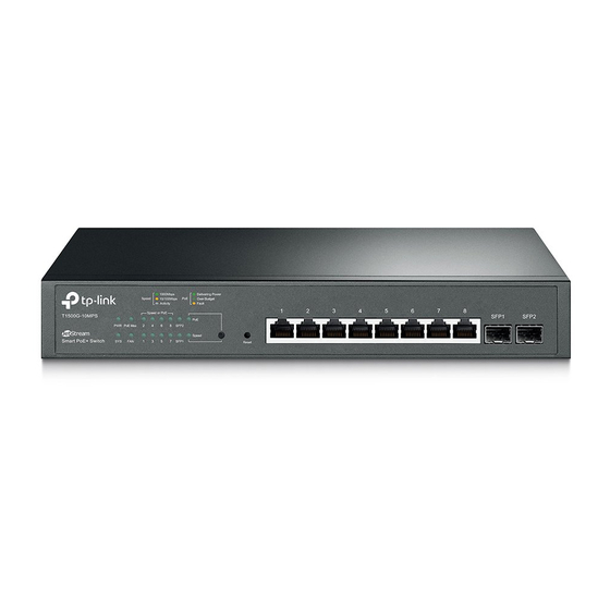
8-port gigabit smart poe+switch with 2 sfp slots
Hide thumbs
Also See for JetStream T1500G-10MPS:
- User manual (242 pages) ,
- Installation manual (24 pages) ,
- How to upgrade (3 pages)

Subscribe to Our Youtube Channel
Related Manuals for TP-Link JetStream T1500G-10MPS


Summary of Contents for TP-Link JetStream T1500G-10MPS
- Page 1 Business Networking Solution Installation Guide JetStream 8-Port Gigabit Smart PoE+Switch with 2 SFP Slots T1500G-10MPS...
- Page 3 FCC STATEMENT This equipment has been tested and found to comply with the limits for a Class A digital device, pursuant to part 15 of the FCC Rules. These limits are designed to provide reasonable protection against harmful interference when the equipment is operated in a commercial environment. This equipment generates, uses, and can radiate radio frequency energy and, if not installed and used in accordance with the instruction manual, may cause harmful interference to radio communications.
- Page 4 BSMI Notice 安全諮詢及注意事項 • 請使用原裝電源供應器或只能按照本產品注明的電源類型使用本產品。 • 清潔本產品之前請先拔掉電源線。 請勿使用液體、 噴霧清潔劑或濕布進行清潔。 • 注意防潮, 請勿將水或其他液體潑灑到本產品上。 • 插槽與開口供通風使用, 以確保本產品的操作可靠並防止過熱, 請勿堵塞或覆蓋開口。 • 請勿將本產品置放於靠近熱源的地方。 除非有正常的通風, 否則不可放在密閉位置中。 • 請不要私自打開機殼, 不要嘗試自行維修本產品, 請由授權的專業人士進行此項工作。 • 此為甲類資訊技術設備, 于居住環境中使用時, 可能會造成射頻擾動, 在此種情況下, 使用者會被要求採 取某些適當的對策。 Industry Canada Statement CAN ICES-3 (A)/NMB-3(A) Explanation of the symbols on the product label Symbol Explanation AC voltage...
- Page 5 Related Document This Installation Guide is also available in PDF on our website. To obtain the latest documentation and product information, please visit the official website: http://www.tp-link.com About this Installation Guide This Installation Guide describes the hardware characteristics, installation methods and the points that should be attended to during the installation. This Installation Guide is structured as follows: Chapter 1 Introduction.
-
Page 6: Table Of Contents
Contents Chapter 1 Introduction ——————————— 01 Product Overview ............01 Appearance ...............01 Chapter 2 Installation ——————————— 05 Package Contents ............05 Safety Precautions ............05 Installation Tools ..............07 Product Installation ............08 Chapter 3 Lightning Protection ——————— 10 Cabling Reasonably............10 Connect to Ground ............12 Equipotential Bonding ...........13 Use Lightning Arrester ..........14 Chapter 4 Connection ———————————... -
Page 7: Chapter 1 Introduction
Smart PoE+ Switch Chapter 1 Introduction Product Overview T1500G-10MPS is compliant with the IEEE802.3 Ethernet protocols. The switch is equipped with powerful management interface, via which system, port, network, VLAN and priority can be configured. They provide a variety of service features and multiple powerful functions with high security. - Page 8 Smart PoE+ Switch LEDs T1500G-10MPS has an LED mode switch button which is for switching the LED status indication. When the Speed LED is on, the port LED is indicating the data transmission status. When the PoE LED is on, the port LED is indicating the power supply status.
- Page 9 Smart PoE+ Switch When the PoE LED is on, the port LED is indicating the power supply status. Status Indication The switch is powered on The switch is powered off or power supply is abnormal Flashing Power supply is abnormal Flashing The switch works properly On/Off...
- Page 10 Smart PoE+ Switch Rear Panel ■ The rear panel of T1500G-10MPS is shown as the following figure. Kensington Security Slot Power Socket Grounding Terminal T1500G-10MPS Figure 1-2 Rear Panel of Kensington Security Slot Secure the lock (not provided) into the security slot to prevent the device from being stolen.
-
Page 11: Chapter 2 Installation
Smart PoE+ Switch Chapter 2 Installation Package Contents Make sure that the package contains the following items. If any of the listed items is damaged or missing, please contact your distributor. One Switch This Installation Guide One Power Cord One Resource CD Two mounting brackets and the fittings Safety Precautions... - Page 12 Smart PoE+ Switch Site Requirements ■ To ensure normal operation and long service life of the device, please install it in an environment that meets the requirements described in the following subsection. Temperature/Humidity 40℃ 0℃ Please keep a proper temperature and humidity in the equipment room. Too high/ low humidity may lead to bad insulation, electricity leakage, mechanical property changes and corrosions.
-
Page 13: Installation Tools
Smart PoE+ Switch Keep the device far from high-frequency, strong-current devices, such as radio ■ transmitting station. Use electromagnetic shielding when necessary. ■ Lightening Protection Extremely high voltage currents can be produced instantly when lightning occurs and the air in the electric discharge path can be instantly heated up to 20,000℃. As this instant cur- rent is strong enough to damage electronic devices, more effective lightning protection measures should be taken. -
Page 14: Product Installation
Smart PoE+ Switch Note: These tools are not provided with our product. If needed, please self purchase them. Product Installation Desktop Installation ■ To install the device on the desktop, please follow the steps: 1. Set the device on a flat surface strong enough to support the entire weight of the device with all fittings. - Page 15 Smart PoE+ Switch 3. After the brackets are attached to the device, use suitable screws (not provided) to secure the brackets to the rack, as illustrated in the following figure. Rack Figure 2-3 Rack Installation Caution: Please set 5~10cm gaps around the device for air circulation. ■...
-
Page 16: Chapter 3 Lightning Protection
Smart PoE+ Switch Chapter 3 Lightning Protection Cabling Reasonably In the actual network environment, you may need cable outdoors and indoors, and the requirements for cabling outdoors and indoors are different. A reasonable ca- bling system can decrease the damage of induced lightning to devices. Note: It 's not recommended using Ethernet cables outdoors. - Page 17 Smart PoE+ Switch Requirements for Cabling Indoors ■ When cabling indoors, keep a certain distance away from the devices that may cause high-frequency interferences, such as down-conductor cable, powerline, power transformer and electromotor. The main cable should be paved in the metal raceway of the access shaft. When ■...
-
Page 18: Connect To Ground
Smart PoE+ Switch Min Parallel Cable Pave Way Length (mm) Parallel cabling 2~5kVA One is in the grounded metal raceway or metal pipe power- line The both are in the grounded metal raceway or metal pipe Parallel cabling >5kVA One is in the grounded metal raceway or metal pipe power- line The both are in the grounded metal raceway or metal... -
Page 19: Equipotential Bonding
Smart PoE+ Switch Note: The grounding bar and the ground cable are not provided with our product. If needed, please self purchase them. Connecting to the Ground via the Power Supply ■ If the device is installed in the normal environment, the device can be grounded via the PE (Protecting Earth) cable of the AC power supply as shown in the following fig- ure. -
Page 20: Use Lightning Arrester
Smart PoE+ Switch The figure below illustrates how to practice equipotential bonding in a network. Grounding Terminal Equipotential Bonding Cable Ground Cable Grounding Bar Figure 3-3 Equipotential Bonding When equipotential bonding, please note that the cable should be copper wrapped Kelly with its area being 6mm at least. - Page 21 Smart PoE+ Switch When purchasing or using a signal lightning arrester, please observe the following rules: The port rate of the signal lightning arrester should match the rate of the desired ■ port on the device. If it is not matched, this signal lighting arrester will not work. Purchase a standard lightning arrester.
-
Page 22: Chapter 4 Connection
Smart PoE+ Switch Chapter 4 Connection Ethernet Port Connect a Ethernet port of the switch to the computer by RJ45 cable as the follow- ing figure shows. RJ45 Port RJ45 Cable Figure 4-1 Connecting the RJ45 Port Verify Installation After completing the installation, please verify the following items: There are 5~10cm of clearance around the sides of the device for ventilation and ■... -
Page 23: Initialization
Smart PoE+ Switch Note: The figure is to illustrate the application and principle. The power plug you get from the package and the socket in your situation will comply with the regulation in your country, so they may differ from the figure above. Initialization After the device is powered on, it begins the Power-On Self-Test. -
Page 24: Appendix A Troubleshooting
Make sure the connected device is turned on and working well. The cable must be less than 100 meters long (328 feet). For more troubleshooting help, go to: http://www.tp-link.com/en/support/faq ■ To download the latest Firmware, Driver, Utility and User Guide, go to: ■... -
Page 25: Appendix B Specifications
Smart PoE+ Switch Appendix B Specifications Item Content IEEE802.3i, IEEE802.3u, IEEE802.3ab, IEEE802.3z, IEEE802.3ad, Standards IEEE802.3af, IEEE802.3at, IEEE802.3x, IEEE802.1p, IEEE802.1q, IEEE802.1x, IEEE802.1d, IEEE802.1s, IEEE802.1w 10Base-T UTP/STP of Cat. 3 or above(maximum 100m) 2-pair UTP/STP of Cat. 5 or above (maximum 100Base-TX 100m) 100Base-FX MMF SFP Module... - Page 28 Website: http://www.tp-link.com Tel: +86 755 26504400 E-mail: support@tp-link.com © 2016 TP-LINK 7106506598 REV1.0.0...
Need help?
Do you have a question about the JetStream T1500G-10MPS and is the answer not in the manual?
Questions and answers