
Subscribe to Our Youtube Channel
Related Manuals for Tektronix MDO4000 Series


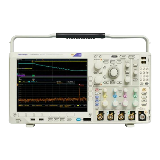
Summary of Contents for Tektronix MDO4000 Series
- Page 1 MDO4000 Series Mixed Domain Oscilloscopes Service Manual *P077058501* 077-0585-01...
- Page 3 MDO4000 Series Mixed Domain Oscilloscopes Service Manual Warning The servicing instructions are for use by qualified personnel only. To avoid personal injury, do not perform any servicing unless you are qualified to do so. Refer to all safety summaries prior to performing service.
- Page 4 Copyright © Tektronix. All rights reserved. Licensed software products are owned by Tektronix or its subsidiaries or suppliers, and are protected by national copyright laws and international treaty provisions. Tektronix products are covered by U.S. and foreign patents, issued and pending. Information in this publication supersedes that in all previously published material.
-
Page 5: Table Of Contents
Front-Panel Board ..................... Adjustments ......................Maintenance......................Preventing ESD ....................Inspection and Cleaning..................Module Removal....................Troubleshooting....................Troubleshooting Procedure .................. Unpacking and Repacking Instructions ..............Replaceable Parts List..................... Parts Ordering Information .................. Using the Replaceable Parts List................MDO4000 Series Mixed Domain Oscilloscopes Service Manual... - Page 6 Table of Contents List of Figures Figure 1: MDO4000 Series block diagram ..............Figure 2: Removing tabs from the front protective cover............. Figure 3: Module locator ..................Figure 4: Primary troubleshooting procedure ..............Figure 5: AC power supply troubleshooting procedure ............
- Page 7 Table 6: Replaceable parts – Rear chassis and connecting modules ........Table 7: Replaceable parts – External parts ..............Table 8: Replaceable parts – cable and connectors, rear chassis ..........Table 9: Replaceable parts – Cable and Connectors, Main board..........MDO4000 Series Mixed Domain Oscilloscopes Service Manual...
-
Page 8: General Safety Summary
Do not operate in an explosive atmosphere. Keep product surfaces clean and dry. Provide proper ventilation. Refer to the manual's installation instructions for details on installing the product so it has proper ventilation. MDO4000 Series Mixed Domain Oscilloscopes Service Manual... - Page 9 DANGER indicates an injury hazard immediately accessible as you read the marking. WARNING indicates an injury hazard not immediately accessible as you read the marking. CAUTION indicates a hazard to property including the product. The following symbol(s) may appear on the product: MDO4000 Series Mixed Domain Oscilloscopes Service Manual...
- Page 10 General safety summary MDO4000 Series Mixed Domain Oscilloscopes Service Manual...
-
Page 11: Preface
Preface This service manual provides information that you need to troubleshoot, disassemble, and replace parts on the following Tektronix oscilloscopes: Model Bandwidth Analog channels RF frequency MDO4104-6 1 GHz 6 GHz MDO4104-3 1 GHz 3 GHz MDO4054-6 500 MHz 6 GHz... - Page 12 Preface viii MDO4000 Series Mixed Domain Oscilloscopes Service Manual...
-
Page 13: Where To Find Operating Information
Where to Find Operating Information For information on installing and operating your oscilloscope, refer to the Tektronix MDO4000 Series Mixed Domain Oscilloscopes User Manual, which was provided with your oscilloscope. This manual is also available, in 11 languages, at www.tektronix.com/manuals. - Page 14 Where to Find Operating Information MDO4000 Series Mixed Domain Oscilloscopes Service Manual...
-
Page 15: Theory Of Operation
The Display system combines live waveform data from acquisition memory with menus and text, and stores this information in display memory. It then uses this data to refresh the XGA display module (LCD). MDO4000 Series Mixed Domain Oscilloscopes Service Manual... -
Page 16: Front-Panel Board
Main board, and controls power to the Main board. The Front Panel board also generates the probe compensation output signal, provides an interface to the application modules, and controls power to the Main board. MDO4000 Series Mixed Domain Oscilloscopes Service Manual... -
Page 17: Figure 1: Mdo4000 Series Block Diagram
Theory of Operation Figure 1: MDO4000 Series block diagram MDO4000 Series Mixed Domain Oscilloscopes Service Manual... - Page 18 Theory of Operation MDO4000 Series Mixed Domain Oscilloscopes Service Manual...
-
Page 19: Adjustments
Please return the instrument to Tektronix if adjustment is required. There are no adjustment procedures (calibrations) that can be performed by the customer. Calibrations can only be performed at a Tektronix service center and require the use of traceable test equipment (signal sources and measuring equipment) to verify the performance of the instrument. - Page 20 Adjustments MDO4000 Series Mixed Domain Oscilloscopes Service Manual...
-
Page 21: Maintenance
Inspection and cleaning are done as preventive maintenance. Preventive maintenance, when done regularly, may prevent oscilloscope malfunction and enhance its reliability. Preventive maintenance consists of visually inspecting and cleaning the oscilloscope and using general care when operating it. MDO4000 Series Mixed Domain Oscilloscopes Service Manual... - Page 22 If any dirt remains, use a cloth or swab dipped in a 75% isopropyl alcohol solution. Use a swab to clean narrow spaces around controls and connectors. Do not use abrasive compounds on any part of the chassis that might damage the chassis. MDO4000 Series Mixed Domain Oscilloscopes Service Manual...
-
Page 23: Table 1: External Inspection Checklist
If any circuit board is repaired or replaced, adjustment is required. (See page 7, Adjustments.) CAUTION. To prevent damage from electrical arcing, make sure that circuit boards and components are dry before applying power to the oscilloscope. MDO4000 Series Mixed Domain Oscilloscopes Service Manual... -
Page 24: Table 2: Internal Inspection Checklist
Dry all parts with low-pressure, deionized air. d. Dry all components and assemblies in an oven or drying compartment using low-temperature (125 °F to 150 °F) circulating air. Lubrication There is no periodic lubrication required for this oscilloscope. MDO4000 Series Mixed Domain Oscilloscopes Service Manual... -
Page 25: Module Removal
Failure to do so could cause serious injury or death. Required Equipment You will need a Torx driver with a T-15 Torx tip to remove instrument screws. MDO4000 Series Mixed Domain Oscilloscopes Service Manual... -
Page 26: Figure 3: Module Locator
fingers. The oils on your fingers will degrade or damage the switch contacts. To help prevent damage to the keypad, use cotton gloves when removing or installing the keyboard pad. Figure 3: Module locator MDO4000 Series Mixed Domain Oscilloscopes Service Manual... -
Page 27: Troubleshooting
When you operate the instrument with the cabinet removed, the system fan will not operate. You must provide an external fan to cool the interior of the instrument. Failure to do so could cause instrument damage. MDO4000 Series Mixed Domain Oscilloscopes Service Manual... -
Page 28: Figure 4: Primary Troubleshooting Procedure
Maintenance Figure 4: Primary troubleshooting procedure MDO4000 Series Mixed Domain Oscilloscopes Service Manual... -
Page 29: Figure 5: Ac Power Supply Troubleshooting Procedure
The test point voltages are printed on the Main board. From left to right in the illustration, they are: +1.225 V, -1.2 V, -2.5 V, +1.5 V, -5 V, +12 V, +1.8 V, +5 VA, +5 VSB, and +2.5 V, +3.3 V, +5 V. MDO4000 Series Mixed Domain Oscilloscopes Service Manual... -
Page 30: Figure 6: Module Isolation Troubleshooting Procedure
Maintenance Figure 6: Module isolation troubleshooting procedure MDO4000 Series Mixed Domain Oscilloscopes Service Manual... -
Page 31: Unpacking And Repacking Instructions
A complete description of the service required Seal the shipping carton with an industrial stapler or strapping tape. Mark the address of the Tektronix Service Center and also your own return address on the shipping carton in two prominent locations. See www.tektronix.com/service to find a service center near you. - Page 32 Maintenance MDO4000 Series Mixed Domain Oscilloscopes Service Manual...
-
Page 33: Replaceable Parts List
Level revision level number. When you order parts, Tektronix will provide you with the most current part for your product type, serial number, and modification (if applicable). At the time of your order, Tektronix will determine the part number revision level needed for your product, based on the information you provide. -
Page 34: Using The Replaceable Parts List
Items in this section are referenced by figure and index numbers to the exploded view Number illustrations that precede the list. Tektronix Part Use this part number when ordering replacement parts from Tektronix. Number 3 and 4 Serial Number Column three indicates the serial number at which the part was first effective. Column four indicates the serial number at which the part was discontinued. -
Page 35: Table 4: Replaceable Parts - Front Panel Assembly
GUIDE, KEY; POLY, BAYBLEND FR-110 213-1149-00 SCREW, TPG, TF; 2-28 X.5, PLASTITE, FLAT HEAD, PHILLIPS, STL, ZNPL 259-0212-00 CIRCUIT, FLEX; 10 KEY 200-5049-00 COVER; OPTION KEY DOOR, 0.7270 X 1.2250 X 0.310, PC/ABS, FR110, SILVER GRAY MDO4000 Series Mixed Domain Oscilloscopes Service Manual... -
Page 36: Figure 7: Exploded View, Front Panel Assembly
Replaceable Parts List Figure 7: Exploded view, Front Panel assembly MDO4000 Series Mixed Domain Oscilloscopes Service Manual... -
Page 37: Table 5: Replaceable Parts - Display, Analog Board, And Main Board
131-7622-00 CONN, RECEPT; GROUND JACK - - - - - - - MAIN BOARD ASSEMBLY. Return the instrument to Tektronix for service. The Main board and the Analog board must be replaced together. - - - - - - - ANALOG BOARD ASSEMBLY. -
Page 38: Figure 8: Display, Analog Board, And Main Board Assembly
Replaceable Parts List Figure 8: Display, analog board, and main board assembly MDO4000 Series Mixed Domain Oscilloscopes Service Manual... -
Page 39: Table 6: Replaceable Parts - Rear Chassis And Connecting Modules
WASHER, LOCK; 0.521 ID, INT, 0.025 THK, STEEL, ZINC FINISH 220-0265-00 NUT, PLAIN, HEX; 0.5-28 X 0.625 065-0861-00 SYSTEM FAN ASSEMBLY, 120 MM, TUBEAXIAL, 12 VDC; SAFETY CONTROLLED, WITH BRACKET 335-1910-00 MARKER, IDENT: SERIAL NUMBER LABEL 335-2248-00 LABEL, IO, REAR MDO4000 Series Mixed Domain Oscilloscopes Service Manual... -
Page 40: Figure 9: Rear Chassis And Connecting Modules
Replaceable Parts List Figure 9: Rear chassis and connecting modules MDO4000 Series Mixed Domain Oscilloscopes Service Manual... -
Page 41: Figure 10: External Parts
Qty. Name and description EXTERNAL PARTS 200-5130-00 FRONT PROTECTIVE COVER 065-0856-00 REAR CASE ASSEMBLY 211-1272-00 SCREW, MACHINE: 6–32 x 0.250, PNH, STL, ZNPL, T-15 TORX DRIVE Figure 10: External parts MDO4000 Series Mixed Domain Oscilloscopes Service Manual... -
Page 42: Figure 11: Rear Chassis, Showing Cables And Connectors
Table 8: Replaceable parts – cable and connectors, rear chassis Figure Serial Serial index Tektronix part no. effective discont'd Qty. Name and description CABLES, REAR CHASSIS 174-5835-00 CABLE ASSEMBLY, LINE INPUT 343-1736-00 CLAMP, CABLE Figure 11: Rear chassis, showing cables and connectors MDO4000 Series Mixed Domain Oscilloscopes Service Manual... -
Page 43: Figure 12: Main Board, Showing Cable And Connectors
Qty. Name and description Cable, Main Board 174-5809-00 CABLE, MAIN BOARD TO FRONT PANEL BOARD 346-0120-00 STRAP, TIEDOWN; 5.5 L MIN, PLASTIC, WHITE Figure 12: Main board, showing cable and connectors MDO4000 Series Mixed Domain Oscilloscopes Service Manual...
Need help?
Do you have a question about the MDO4000 Series and is the answer not in the manual?
Questions and answers