Toa VX-3150DS Operating Instructions Manual
Power supply manager
Hide thumbs
Also See for VX-3150DS:
- Installation manual (162 pages) ,
- Operating instructions manual (36 pages)
Table of Contents
Advertisement
Quick Links
OPERATING INSTRUCTIONS
POWER SUPPLY MANAGER
VX-3150DS
1134
TOA Electronics Europe GmbH
Suederstrasse 282, 20537 Hamburg, Germany
1134-CPR-137
DoP 16-005
EN 54-4: 1997 + A1: 2002 + A2: 2006
Fire Detection and fire alarm systems - part 4: power supply equipment
Thank you for purchasing TOA's Power Supply Manager.
Please carefully follow the instructions in this manual to ensure long, trouble-free use of your equipment.
Advertisement
Table of Contents

Related Manuals for Toa VX-3150DS


Summary of Contents for Toa VX-3150DS
- Page 1 EN 54-4: 1997 + A1: 2002 + A2: 2006 Fire Detection and fire alarm systems - part 4: power supply equipment Thank you for purchasing TOA’s Power Supply Manager. Please carefully follow the instructions in this manual to ensure long, trouble-free use of your equipment.
-
Page 2: Table Of Contents
Front (with the front panel removed) ................6 Rear ..........................7 4. INSTALLATION ....................8 4.1. Installing the VX-3150DS in the Cabinet Rack ............. 8 4.2. Battery Installation ....................8 4.3. Affixing Declaration of Compliance (EN 54-4 Standard) ........12 5. CONNECTIONS .................... -
Page 3: Safety Precautions
AC power plugs (AC CAUTION power cords), disconnect the battery, and contact your nearest TOA dealer. Make no further attempt to operate the unit in this condition as this may When Installing the Unit cause fire or electric shock. -
Page 4: Features
• Automatically switches to the backup power supply when the AC Mains power supply is interrupted. • Detects charging circuitry or battery failures, and transmits failure signals to the DS LINK of the TOA Voice Evacuation Systems (VX-2000, SX-2000, VM-3000, and VX-3000). -
Page 5: Nomenclature And Functions
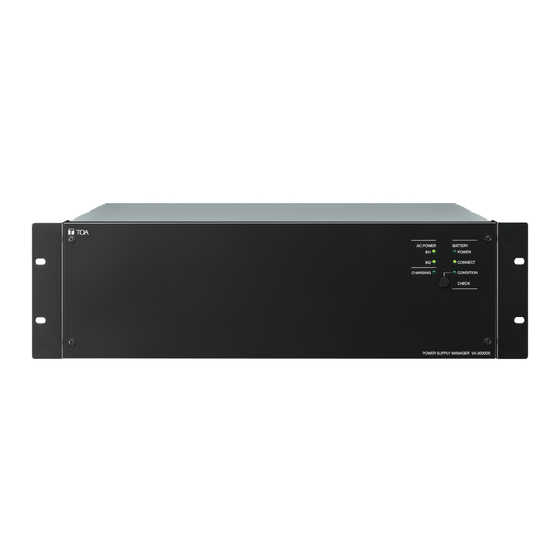
BATTERY POWER CONNECT CHARGING CONDITION CHECK POWER SUPPLY MANAGER VX-3150DS 1. Power indicators [AC POWER IN] Note Light green when AC power is supplied through the Battery check cannot function for 1 minute during AC inlet (18). of which Battery indicator (3) flashes twice, pause, and then repeats after it has been activated once. -
Page 6: Front (With The Front Panel Removed)
Places the unit in AC operation mode or battery Used for terminating the connection. mode. Set to ON when no other VX-3150DS unit is ON: All power outputs are shut down when AC connected or when this unit is the last one of power fails even if backup batteries are connected units. -
Page 7: Rear
The temperature sensor has a serial number label 2 x Panasonic LC-XB12100P* attached to it. 2 x Yuasa NP65-12 When connecting the temperature sensor to this 2 x Yuasa NPL100-12 terminal, confirm the serial number matches that * Compliant with EN54-4 of the VX-3150DS. -
Page 8: Installation
4. INSTALLATION 4.1. Installing the VX-3150DS in the Cabinet Rack Rack mounting screw 5 x 12 4.2. Battery Installation WARNING • Take special care to prevent the battery from being shorted by misconnection of the battery cable. If the short occurs, the unit may fail. - Page 9 • Insert the battery cable into the correct position in the battery terminal referring to the terminal's cross sectional diagrams below. Correct position of the cable insertion Incorrect position of the cable insertion Wrong insertion position of the cable or a forked cable insertion causes poor contact or insufficient Cable conductor connection tightness, making the cable come off to...
- Page 10 4.1 – 5.6 Nm (M6) 8.2 – 5.6 Nm (M8) Step 1. Allow more than 10 seconds to elapse after removing the power cords from the VX-3150DS' rear- mounted AC inlet. Step 2. Insert the positive battery cable into the VX-3150DS' rear-mounted BATTERY POWER IN positive terminal from the bottom side of the connector, then tighten the terminal screw with a flat screwdriver.
- Page 11 [Disconnecting the battery] Step 1. Confirm that battery power is not in use by means of the VX-3150DS' front-mounted BATTERY POWER LED, which is unlit in this case. Step 2. Loosen the VX-3150DS' BATTERY POWER IN negative terminal screw, then pull out the negative battery cable.
-
Page 12: Affixing Declaration Of Compliance (En 54-4 Standard)
4.3. Affixing Declaration of Compliance (EN 54-4 Standard) To declare that the VX-3150DS complies with EN 54-4, affix the sticker supplied with the VX-3150DS visible to the front panel of the equipment (e.g. at the upper right side as shown below). -
Page 13: Connections
5. CONNECTIONS 5.1. Connecting the VX-3150DS to VX-2000 System VX-2000 AUDIO LINK DATA LINK Ferrite cable clamp* DC POWER IN VX-2000SF Cat. 5 STP DS-SF LINK DC POWER IN VP-2000 series or VP-3000 series power amplifier DC POWER IN From VX-3150DS 28 V 4.8 A... -
Page 14: Connecting The Vx-3150Ds To Sx-2000 System
5.2. Connecting the VX-3150DS to SX-2000 System 5.2.1. When using a redundant power system* In this connection example, 2 power supply units are used. Even if one of the 2 units fails or its power supply line is broken, power is still supplied from the other unit, preventing the system from going down. - Page 15 PA OUT (SP LINE) VP-3154, VP-3304, or VP-3504 x 2 CH* * VP-3504 x 2 CH: That only 2 channels can be used when VP-3504 connect to VX-3150DS. Note To supply DC power to each component such as SX-2100AO and SX-2000SM except power amplifiers, the...
- Page 16 5.2.3. DS LINK terminal connections Connect the DS LINK terminal of the VX-3150DS to the DS Link terminal of the SX-2000SM or SX-2100AO. The figure below shows a connection example when the VX-3150DS units are connected to the SX-2100AO. This connection also applies to the SX-2000SM.
-
Page 17: Connecting The Vx-3150Ds To Vm-3000 System
5.3. Connecting the VX-3150DS to VM-3000 System From VX-3150DS Note VM-3240VA/3360VA Remove the short bar attached at the factory. 230 V AC 220 V AC 50/60 Hz VP-2241 From DC POWER IN VX-3150DS 28 V 4.8 A PA OUT (SP LINE) - Page 18 One VX-3150DS is required every 2 VM-3360VA/3360E amplifiers or 3 VM-3240VA/3240E amplifiers. No. of VM-3360VA/3360E No. of VX-3150DS units No. of VM-3240VA/3240E No. of VX-3150DS units Below is an example showing that one VX-3150DS is used in a system including 3 VM amplifiers. VM-3240VA VM LINK VM-3240E VX-3150DS...
- Page 19 No. of VM-3360VA/3360E No. of VX-3150DS units No. of VM-3240VA/3240E No. of VX-3150DS units Below is an example showing that one VX-3150DS unit is used in a system including 3 VM amplifiers. VM-3240VA EXT. AMP INPUT VM LINK VP-3304, VP-2241, EXT.
- Page 20 One VX-3150DS is required every 2 VM-3360VA/3360E amplifiers or 3 VM-3240VA/3240E amplifiers. No. of VM-3360VA/3360E No. of VX-3150DS units No. of VM-3240VA/3240E No. of VX-3150DS units Below is an example showing that 2 VX-3150DS units are used in a system including 5 VM-3240VA/3240E amplifiers. No.1 VM-3240VA VX-3150DS DS LINK DC POWER EXT.
-
Page 21: Connecting The Vx-3150Ds To Vx-3000 System
If the shore occurs, the unit may fail. 230 V AC 220 V AC 50/60 Hz Note The VX-3150DS’ “POWER OUT 19 – 33 V MAX 5 A” terminal cannot be used for connecting the Digital amplifier modules with the VX-3150DS. - Page 22 5.4.2. DS LINK terminal connections Connect the DS LINK terminal of the VX-3150DS to the DS Link connectors of the VX-3004F, VX-3008F, or VX-3016F. The figure below shows a connection example when the VX-3150DS units are connected to the VX- 3004F.
-
Page 23: Cable Usage Table
24 V (16-25 V) RM-200M DC IN DC jack screw terminal cable end Inner diameter: MAX 0.3 A F2.1 mm Length: 9.5 mm) * VP-3504 x 2 CH: That only 2 channels can be used when VP-3504 connect to VX-3150DS. -
Page 24: Switching Off System Power (Dc)
• VX-3150DS' DS LINK Connections Connector Name RJ45 Pin No. Colour Pair Assignment Direction/Level DS LINK IN/OUT Orange/white Connection Check Orange Battery Failure Green/white Charging Circuitry Failure Output/0 – 3.3 V Blue DC Off Blue/white AC Off Green 3.3 V DC Input Input (DC)/3.3 V... -
Page 25: Block Diagram
8. BLOCK DIAGRAM Control Connector [DS LINK IN] Control Connector Fuse RESET [DS LINK OUT] Control Circuit AC 250 V SWITCH T8A H SMPS* BATTERY TEMPERATURE SENSOR IN BATTERY CONNECT Battery Connection Terminal [BATTERY AC POWER IN POWER IN] PFC* POWER OUT DC24 V 24 V (16-25 V) MAX 0.3 A... -
Page 26: Appendix
9. APPENDIX: Recommendations to the Power Supply Installation Incorrect installations of the power supply manager VX-3150DS and its related equipment as batteries can cause unnecessary fault indications. This information sheet gives you helpful hints and recommendations to avoid it. Please also take care on the battery handling hints. - Page 27 1. Connect the plus terminal of the battery to the VX-3150DS (check on correct polarity and fixation in the battery cable clamp at the VX-3150DS).
- Page 28 VX-3150DS The power manager VX-3150DS monitors the availability of the AC power and switches on the battery in case of a total loss of that power. When the AC power is available, then the batteries will be charged. The charge current is monitored, and when it is below 2 mA, then a charger fault will be entered into the log file of the system.
- Page 29 (2) seconds only. Measure of the voltage of each cable path after depressing the battery check button of the VX-3150DS. When A fuse vis in the path must be included in the measurement. Proceed one measurement per minute maximum.
- Page 30 This measurement can be done with a slow voltmeter. Disconnect the VA unit’s power supply from the DC output from the VX-3150DS and connect a load of 5 - 6 Ω / 600 W to the DC output (when the current of the connected system components is known), then take care that the total current is approximately 5 A.
-
Page 31: Specifications
10. SPECIFICATIONS Power Source 220 – 230 V AC, 50/60 Hz Power Consumption 1460 W max. in total (at rated output with charging) 460 W max. (EN60065) DC Power Output (AC Rated output: 1140 W (total DC power output) mode) Peak output: 1280 W (total DC power output) Current Specification Maximum output current from the battery : 25 A... - Page 32 This equipment is compliant with Class A of CISPR 32. In a residential environment this equipment may cause radio interference. Traceability Information for Europe Manufacturer: Authorized representative: TOA Corporation TOA Electronics Europe GmbH 7-2-1, Minatojima-Nakamachi, Chuo-ku, Kobe, Hyogo, Japan Suederstrasse 282, 20537 Hamburg, Germany...
- Page 36 URL: https://www.toa.jp/ 133-02-00250-04...
Need help?
Do you have a question about the VX-3150DS and is the answer not in the manual?
Questions and answers