Toa VX-2000DS Instruction Manual
Emergency power supply
Hide thumbs
Also See for VX-2000DS:
- Instruction manual (32 pages) ,
- System design manual (113 pages) ,
- Installation manual (16 pages)
Table of Contents
Advertisement
Quick Links
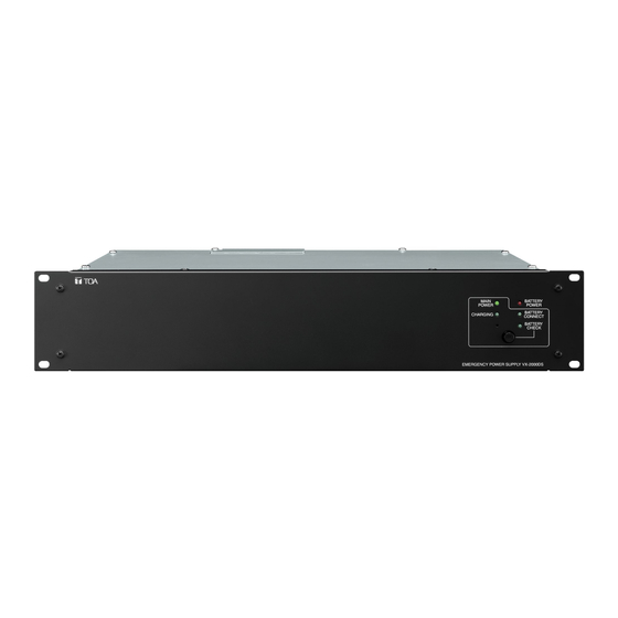
EMERGENCY POWER SUPPLY
TABLE OF CONTENTS
Thank you for purchasing TOA's Emergency Power Supply.
Please carefully follow the instructions in this manual to ensure long, trouble-free use of your equipment.
.... 2
........................... 3
....... 5
........................ 7
.................. 11
INSTRUCTION MANUAL
............................................ 13
VX-2000DS
.................... 12
................................... 14
.................................... 15
Advertisement
Table of Contents

Related Manuals for Toa VX-2000DS


Summary of Contents for Toa VX-2000DS
-
Page 1: Table Of Contents
......7 9. SPECIFICATIONS ........15 5. CONNECTIONS WHEN USING WITH THE VM-3000 SYSTEM ....11 Thank you for purchasing TOA's Emergency Power Supply. Please carefully follow the instructions in this manual to ensure long, trouble-free use of your equipment. -
Page 2: Important Safety Instructions
1. IMPORTANT SAFETY INSTRUCTIONS • Read these instructions. • Keep these instructions. • Heed all warnings. • Follow all instructions. • Do not use this apparatus near water. • Clean only with dry cloth. • Do not block any ventilation openings. Install in accordance with the manufacturer's instructions. •... -
Page 3: Safety Precautions
(or circuit breaker), disconnect the battery, and contact AVERTISSEMENT your nearest TOA dealer. Make no further attempt Indique une situation risquant d’entraîner des to operate the unit in this condition as this may blessures graves, voire la mort, en cas de cause fire or electric shock. - Page 4 AC outlet, ensure that the total load current never exceeds the AC outlet's allowable current capacity. · The VX-2000DS can be mounted in an EIA- Standard equipment rack (2 U* size). * 2 U size = 89 mm (reference size) ·...
-
Page 5: Nomenclature And Functions
3. NOMENCLATURE AND FUNCTIONS • Detects charging circuitry or battery failures, and transmits failure signals to the DS LINK of the VM-3000 TOA Voice Evacuation System. • Keeps a 2 x 12 V sealed lead-acid battery charged while maintaining temperature compensation for the charging voltage. - Page 6 3. Battery indicator [BATTERY POWER] 8. PS detect switches Indicates the state of battery usage. Lights red Always connect a power supply to the terminals when the DC power supply is interrupted and 1 + 2 of the DC INPUT. When connecting a switched over to the backup power supply.
-
Page 7: Battery Installation
4. BATTERY INSTALLATION WARNING • Take special care to prevent the battery from being shorted by misconnection of the battery cable. If the short occurs, the unit may fail. Follow the instructions in this section for safe and secure connection. •... - Page 8 To prevent the battery cable from being shorted to the rear panel due to misconnection, attach the supplied insulating sheet in place following the procedures below. VX-2000DS Step 1. Remove the screw indicated by the arrow. Step 2. Put the supplied insulating sheet over the battery terminals, and fix it with the removed screw.
- Page 9 4.1 – 5.6 Nm (M6) 8.2 – 5.6 Nm (M8) Step 1. Allow more than 10 seconds to elapse after removing the power cord from the VX-2000DS' rear- mounted AC inlet. Step 2. Insert the positive battery cable into the VX-2000DS' rear-mounted BATTERY POWER IN positive terminal from the bottom side of the connector, then tighten the terminal screw with a flat screwdriver.
- Page 10 [Disconnecting the battery] Step 1. Confirm that battery power is not in use by means of the VX-2000DS' front-mounted BATTERY POWER LED, which is unlit in this case. Step 2. Loosen the VX-2000DS' BATTERY POWER IN negative terminal screw, then pull out the negative battery cable.
-
Page 11: Connections When Using With The Vm-3000 System
Applicable Battery: Panasonic LC-X/LC-P Series (12 V x 2) Le courant de charge de l'unité VX-2000DS est de 5 A au maximum. Note Make PS2 and PS3 switch settings according to the total number of connected power supply units VM-3240VA and VM-3240E (power supply unit incorporated);... -
Page 12: Connection Cable List
One VX-2000DS is required every 3 VM amplifiers. Number of VX-2000DS units Number of VM amplifiers Min. [Ah] Battery capacity Max. [Ah] Below is an example showing that one VX-2000DS is used in a system including 3 VM amplifiers. VM-3240VA VM LINK VM-3240E VM LINK VX-2000DS... -
Page 13: Switching Off System Power (Dc)
This permits the system power to be switched off without switching over to battery operation. Note Never stop the AC power supply to the VX-2000DS as doing so causes the system power source to be maintained by the battery. VX-2000DS... -
Page 14: Block Diagram
8. BLOCK DIAGRAM Control Connector [DS-SF LINK] BATTERY DC Detect CONNECT Indicator DC Input [PS IN] (150 A max.) DC Input 1 Control Circuit DC Input 2 DC Input 3 DC Input 4 DC Input 5 DC Input 6 Battery Connection Terminal [BATTERY POWER IN] Fuse... -
Page 15: Specifications
9. SPECIFICATIONS Power Source 120 V AC, 60 Hz Power Consumption 240 W max. Applicable Battery Panasonic LC-X/LC-P Series (12 V x 2) Charging Method Trickle charging Charging Current 5 A max. Charging Output Voltage 27.3 V ±0.3 V (at 25°C) Temperature correction coefficient: –40 mV/°C Power Supply Input 6, M4 screw terminal, distance between barriers: 11 mm... - Page 16 Modifications Any modifications made to this device that are not approved by TOA Corporation may void the authority granted to the user by the FCC to operate this equipment.
Need help?
Do you have a question about the VX-2000DS and is the answer not in the manual?
Questions and answers