DKS 6002 Installation Instructions Manual
Vehicular swing gate operator
Hide thumbs
Also See for 6002:
- Owner's manual (41 pages) ,
- Installation manual (28 pages) ,
- Owner's manual (34 pages)
Table of Contents
Advertisement
Quick Links
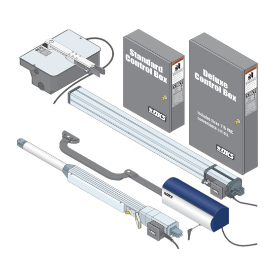
Actuator Arm and
Control Box Mounting
To wire this operator and complete the installation, refer to a specific control box "Wiring/Owner's manual".
EXTERNAL ENTRAPMENT PROTECTION MUST be
installed or the gate operator WILL NOT function.
UL 325 Compliant
Vehicular Swing Gate Operator
Copyright 2016 DoorKing, Inc. All rights reserved.
6002
6002
6002
6002-065-B-3-16
Advertisement
Table of Contents

Related Manuals for DKS 6002


Summary of Contents for DKS 6002
- Page 1 Actuator Arm and 6002 6002 6002 Control Box Mounting Vehicular Swing Gate Operator To wire this operator and complete the installation, refer to a specific control box “Wiring/Owner’s manual”. 6002-065-B-3-16 EXTERNAL ENTRAPMENT PROTECTION MUST be installed or the gate operator WILL NOT function.
-
Page 3: Specifications
6002 SPECIFICATIONS Class of Operation Model 6002 - UL 325 Class I Type of Gate Vehicular Swing Gates Only Actuator Arm Voltage 24 VDC Current 3 Amps Motor RPM 1400 Maximum Thrust 300 daN Max Gate Weight 500 Lbs. Max Gate Length... -
Page 4: Table Of Contents
Gate “Opens to the Inside” Installation Gate “Opens to the Outside” Installation Mounting Actuator Arm Mounting Control Box with Conduit 13-14 Install Warning Signs In-Ground Loops Entrapment Protection Positions “Opens to the Inside” Accessory Items 6002 Primary/Secondary 4302 Circuit Board Connection 6002-065-B-3-16... -
Page 5: Astm F2200 Standard For Gate Construction
2. Care shall be exercised to reduce the risk of nuisance tripping, such as when a vehicle trips the sensor while the gate is still moving in the opening direction. 3. One or more non-contact sensors shall be located where the risk of entrapment or obstruction exist, such as the perimeter reachable by a moving gate or barrier. 6002-065-B-3-16... -
Page 6: Important Notices
Do not allow children to play in the area of the operator or to play with any gate-operating device. • To remove the gate operator from service, operate the gate to the full open position and then shut off power to the operator at the service panel. 6002-065-B-3-16... -
Page 7: Ul 325 Entrapment Protection
Type C - Inherent force limiting, inherent adjustable clutch or inherent pressure relief device. Type D - Actuating device requiring constant pressure to maintain opening or closing motion of the gate. * B1 and B2 means of entrapment protection must be MONITORED. 6002-065-B-3-16... -
Page 8: Glossary
ENTRAPMENT - The condition when an object is caught or held in a position that increases the risk of injury. 6002-065-B-3-16... -
Page 9: Swing Gate Requirements
NOT required for this area. If distance is less than 16 inches, entrapment protection in this area is required. ASTM F2200 7.1.1.2 Not Allowed Gates shall have smooth bottom edges, with vertical bottom edged protrusions not exceeding 0.50 inches. ASTM F2200 4.3 6002-065-B-3-16... -
Page 10: Swing Gate Protection
Number and placement of loops is Monitored device dependent on the application. helps protect against entrapment when needed. Automatic Exit Loop (Optional) will provide an open command to the gate operator(s) when a vehicle is exiting the REQUIRED property. for operator to function. 6002-065-B-3-16... -
Page 11: Installation
(See Swing Gate Requirements on page 7). Manual Release Actuator cover removed. 0 ° Insert allen wrench Use key to unlock and remove the cover. Remove allen wrench from inside of cover. and turn 180° to release the arm. 6002-065-B-3-16... -
Page 12: Gate "Opens To The Inside" Installation
Actuator arm MUST be level! Middle Bottom Installation Note: Make sure that the operator is mounted high enough off the ground that it will NOT come Bottom in contact with standing or flowing water. This will Gate in Closed Position damage the operator. 6002-065-B-3-16... -
Page 13: Gate "Opens To The Outside" Installation
Note: Make sure Actuator arm MUST be level! that the operator is mounted high enough off the Middle ground that it will NOT come in contact with standing or flowing Bottom water. This will damage the Gate in Closed Position operator. 6002-065-B-3-16... -
Page 14: Mounting Actuator Arm
Protect the arm from welding sparks during tack welding. Remove arm before completely welding around the brackets. Make sure the brackets are level when tack welding them! The arm will not operate properly if not level. Actuator arm MUST be level! 6002-065-B-3-16... -
Page 15: Mounting Control Box With Conduit
Dual Actuators Connection (115 VAC or Solar) Secondary Actuator SECONDARY Actuator PRIMARY Actuator Cable Junction Interconnection Cable 30 feet. P/N 2600-755 Primary Interconnection Cable 40 feet. P/N 2600-756 Actuator Interconnection Cable 50 feet. P/N 2600-757 Cable DoorKing interconnection cable (Sold separately) inside underground conduit 6002-065-B-3-16... - Page 16 Typical conduit To attach post to concrete, configuration DoorKing recommends four (4) 3/8” x 3” sleeve anchors (not supplied). (not supplied). Do Not mount post on asphalt. 6002-065-B-3-16...
-
Page 17: Install Warning Signs
Reverse loops work in conjunction with completely opened by the time reverse the cycling of the gate while a vehicle the shadow loop and both should be used. you drive up to it (Free exit). is in or near the gate’s swing pathway. 6002-065-B-3-16... -
Page 18: Entrapment Protection Positions "Opens To The Inside
MONITORED entrapment protection device is REQUIRED. Closing Gate Potential Entrapment Area: If the CLOSING gate could cause an entrapment, then installation of a MONITORED entrapment Monitored protection device is REQUIRED. Reversing Monitored Edge Potential Photo Sensor Entrapment Area 6002-065-B-3-16... -
Page 19: Accessory Items
Accessory Items UL 325 Monitored Entrapment Protection Devices available for the model 6002 swing gate operator. Type B2 Contact Sensors (Reversing Edge) Miller Edge Sensing Edges - all models with a T2 (resistive) termination. Miller Edge Monitored Gate Link Model MGL-K20... -
Page 20: 6002 Primary/Secondary 4302 Circuit Board Connection
6002 Primary/Secondary 4302 Circuit Board Connection Brown 1 Blue 2 Beam Edge Orange 3 Motor Motor Red 4 Yellow 5 Beam Green 6 Edge 1476-010 Green/Yellow 7 Secondary 1 2 3 4 5 6 7 1 2 3 4 5 6 7... - Page 21 6002-065-B-3-16...
- Page 22 Actuator Arm and 6002 6002 6002 Control Box Mounting Vehicular Swing Gate Operator To wire this operator and complete the installation, refer to the specific control box “Wiring/Owner’s manual”. 6002-065-B-3-16 www.doorking.com DoorKing, Inc. 120 S. Glasgow Avenue Inglewood, California 90301 U.S.A.
Need help?
Do you have a question about the 6002 and is the answer not in the manual?
Questions and answers