Table of Contents
Advertisement
Quick Links
Advertisement
Table of Contents

Related Manuals for Amrel RK886EX


Summary of Contents for Amrel RK886EX
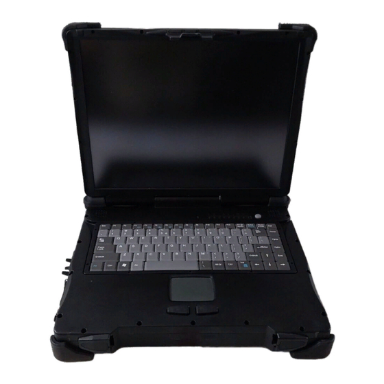
- Page 1 American Reliance, Inc. 15.1” NOTEBOOK COMPUTER RK886EX USER’S GUIDE...
- Page 2 Copyright © 2008 American Reliance, Inc. All rights reserved. No part of this publication may be processed; such as reproduced, transmitted, transcribed, stored in a retrieval system, translated into any computer language in any form, or by any means of electronic, mechanical, magnetic, optical, chemical, or others without the prior written permission of the manufacturer.
- Page 3 EMC and Safety Notice Federal Communications Commission Statement This equipment has been tested and found to comply with the limits for a class B digital device, under part 15 of the FCC Rules. These limits are designed to provide reasonable protection against harmful interference in a residential installation.
- Page 4 Important Note FCC RF Radiation Exposure Statement: This equipment complies with FCC RF radiation exposure limits set forth for an uncontrolled environment. This device and its antenna must not be co-located or operated with any other antenna or transmitter. Products with the CE Marking comply with both the EMC Directive (89/336/EEC) and the Low Voltage Directive (73/23/EEC) issued by the Commission of the European Community.
- Page 5 Is herewith confirmed to comply with the requirements set out in the Council Directive on the approximation of the laws of the member states relating to Electromagnetic Compatibility (89/336/EEC), Low-voltage Directive (73/23/EEC) and the Amendment Directive (93/68/EEC), the procedures given in European Council Directive 99/5/EC and 89/3360EEC.
- Page 6 Power Conservation This computer consumes much less power than conventional computers. However, power consumption may be reduced by properly configuring the Power Management Setup. It is recommended the power saving functions be enabled even when not running on battery power. Power Management does not degrade performance while saving power.
-
Page 7: Table Of Contents
CONTENTS GETTING STARTED ........................1 ........................... 1 NPACKING ........................2 UICK PERATION ......................3 ONTROLS AND NDICATORS USEFUL INFORMATION ......................7 ............................. 7 OCATION ..........................7 UGGEDNESS ........................8 PERATING YSTEMS AC A ..........................8 DAPTER ............................9 ATTERY POST ........................11 P AND .................... - Page 8 PCMCIA C ........................22 OVER ........................22 EHICLE DAPTER ......................22 ATTERY HARGER ..........................22 NDER SPECIFICATIONS ........................23 CPU ............................23 ............................. 23 EMORY ............................23 ISPLAY ..........................24 EYBOARD ........................24 RIVE ........................... 24 OUCH CREEN ............................ 24 PORTS AC A ..........................
- Page 9 ......................47 OUCH CREEN RIVER CD-ROM D ........................48 RIVER PCMCIA D ........................48 RIVER PCI 1G AX92200 LAN ...................... 48 PCI INT8100 LAN......................48 PCI-E 1G RTL8111B LAN ....................48 PCI-E I 3945ABG WLAN ..................48 NTEL ......................49 ODEM RIVER ........................
-
Page 10: Getting Started
Getting Started GETTING STARTED Unpacking The following components come with your computer. If anything is missing or damaged, please notify the dealer immediately. Computer unit Removable drive installed on computer (CD-ROM/DVD) AC Adapter AC Power Cord Utility CD User's Guide External Keyboard Adapter Cable Printer adapter cable Carrying Bag... -
Page 11: Quick Operation
Getting Started Quick Operation Loosen the battery screw, remove the battery insulation sheet, and mount the battery. Attach the AC adapter and charge battery for at least 10 minutes. Turn ON the computer by pressing the power switch momentarily. Notice: When ambient temperature is under 0℃, the system may not boot up immediately. -
Page 12: Controls And Indicators
Getting Started Controls and Indicators Controls and Indicators (Upper) 1. Heater 2. BT/WLAN/GPS 3. Keyboard Number Lock... - Page 13 Getting Started 4. Keyboard Caps Lock 5. Keyboard Scroll Lock 6. HDD in use 7. Secondary Battery Charge 8. Primary Battery Charge 9. Power indicator 10. Power switch 11. Touch pad left button 12. Touch pad 13. Touch pad right button Controls and Indicators (Right) CD-ROM Drive Configuration: 1.
- Page 14 Getting Started eft)-Standard Controls and Indicators (L 1. External Keyboard + PS/2 port 2. LAN Jack 3. IEEE1394 port (Fire Wire) 4. IEEE1394 port 5. USB port (Universal Serial Bus) 6. USB port (Universal Serial Bus) 7. 1x Express and 1x PCMCIA Slots (Option: 2x PCMCIA) 8.
- Page 15 Getting Started Controls and Indicators (Rear) 1. Optional Military connector port 2. Optional Military connector port 3. DC Power Jack 4. External DVI port 5. External RGB Port 6. Printer Port 7. Docking Port 8. Serial Port COM2 9. Serial Port COM1...
-
Page 16: Useful Information
Useful Information USEFUL INFORMATION Location A clean and moisture-free environment is preferred. Make room for air circulation. Avoid areas with: Sudden or extreme changes in temperature. Extreme heat. Strong electromagnetic fields (near television set, motor rotation area, etc.). Dust or high humidity. If it is necessary to work in a hostile environment, please regularly maintain your computer by cleaning dust, water, etc. -
Page 17: Operating Systems
Useful Information Operating Systems The computer is compatible with most operating systems (OS). However, not all functions are 100% compatible. For example, ACPI, APM, Smart Battery, etc. are not available on DOS, Windows NT, and other non-Microsoft OS. Consequently “Standby”, “Hibernation”, “Battery Gauge”, etc. would not work under such operating systems. -
Page 18: Battery
Useful Information Battery The computer will automatically switch to battery when the external power source (AC adapter or optional vehicle adapter) is disconnected. Battery Power Saving Tips The computer comes with an intelligent power-saving feature. You may extend the battery life by: Setup power saving functions in Operating System Power Management options (e.g. - Page 19 Useful Information Note: Battery characteristic varies depending on factors such as ambient temperature, charging method, load current, aging, etc. For example, the chemicals of the battery are more inactive at low temperature, thus decreases the output power. The battery gauge should only be used as a reference. Please do not expect it to show the exact amount of the power remaining.
-
Page 20: Boot Up And Post
Useful Information Boot Up and POST The computer turns ON and loads the operating system (such as Windows) into the system memory. This start-up procedure is called “boot up”. The ROM BIOS Power On Self-Test (POST) Each time the computer powers on, it automatically performs a self-test of its memory and hardware devices. -
Page 21: Dvi
Useful Information LCD and DVI monitor simultaneous display needs both BIOS and Windows settings. BIOS setting: Advanced->Boot up display->"EFP" or "CRT+EFP" (EFP=DVI) The available BIOS options are as follows only: CRT+LCD CRT+EFP (No simultaneous LCD+CRT+EFP) Windows setting: Control panel -> Intel(R) Extreme Graphics -> select under Device Display resolution of notebook LCD and DVI monitor must be identical. - Page 22 Useful Information 3. Use a coin to turn and loose the screws on the modules. 4. Remove the battery from the compartment. 5. Push the latch knob to release the CD-ROM or HDD module and push them outward. 6. Remove the module from the computer. To re-install the modules: Gently push the module into the slot.
-
Page 23: Components And Functions
Components and Functions COMPONENTS AND FUNCTIONS Keyboard The keyboard is functionally equivalent to a full size desktop keyboard. A sample key layout is shown below. The Numeric Keypad The numeric keypad functions like an electronic calculator. It is embedded in the main keyboard, with the numeric figures printed on the upper right of their respective keys. -
Page 24: Printer Cable
Components and Functions Keyboard Backlight (optional) Press [Fn] [F5] key for approximately 1 second turns keyboard backlight ON or OFF. Printer Cable For most printers there is no special requirement in connection. However, some printer cables do not contain all 25 wires. To avoid malfunction, the printer adapter cable comes with your computer should be attached to the printer cable. -
Page 25: Cd-Rom Drive
Components and Functions CD-ROM Drive The CD-ROM drive is a standard IDE ATAPI type, which accepts a variety of standard 12cm CDs such as CD-ROM, audio CD, CD-I, Photo CD, video CD, etc. The following procedure assumes that all the necessary CD-ROM utilities were installed on the computer. - Page 26 Components and Functions Ports (horizontal version, ports on rear) 1. COM2 2. COM1 3. USB #1 & #2 4. ANT. (Reserved) 5. RGB 6. DVI 7. LAN (Sealed / No function) 8. PS/2 9. DC jack Mount the DockUnder: 1. Turn OFF the power. 2.
- Page 27 Components and Functions Note: Do not lift up the computer while engaging.
- Page 28 Components and Functions Pull up the metal bar. Move forward inside. Lock along the direction of the clock. Key Locked with Electric Power ON/OFF. While turn on the power of DockUnder with the Key that can use all the functions on DockUnder. Meantime Computer will also have the power. There are 2*PCI+1*PCIe slots on the DockUnder.
- Page 29 Components and Functions To install expansion card in DockUnder: Unplug the AC adapter. Release and remove the computer. Remove the screws on the upper and lower covers. Open the upper cover. Install the expansion card into the slot and fix the L-bracket. Assemble the upper cover.
-
Page 30: Optional Devices
Optional Devices OPTIONAL DEVICES Memory Card The memory card will expand your memory to facilitate better system performance. The cards are available as following: 1 GB, 2 GB Battery A Lithium Ion rechargeable 2 battery may install into the CD-ROM compartment. -
Page 31: Nd Hdd
Optional Devices Swappable with CD-ROM drive. Set as IDE primary slave drive. Touch Screen Resistive touch screens for direct finger touch or pen input instead of mouse or touch pad. PCMCIA Cover Besides the attached PCMCIA rubber cover, there is an optional cover with a metal frame that can be fixed using screws. -
Page 32: Specifications
Specifications SPECIFICATIONS Intel Core2 Duo (Merom) CPU runs at multiple speeds dependent on CPU type and operating system: The CPU speed switches automatically by detecting AC adapter/battery operation and busy state. Memory System memory Standard: 512MB Expandable: 4GB (2GBx 2) Cache memory Internal Level-2 2MB Video memory... -
Page 33: Keyboard
Specifications Keyboard Number of keys: Key travel: 2.8 mm Function: Emulates standard 101/102-key keyboard * Optional Backlight Rubber Keyboard Number of keys: Key travel: 1.5 mm Function: Emulates standard 101/102-key keyboard Hard Disk Drive 2.5” Type: Interface: Serial ATA Touch Screen Type: Resistive Interface:... -
Page 34: Ac Adapter
Specifications AC Adapter Voltage: AC 90~240 V Frequency: 50/60 Hz Output Voltage: DC 19V Maximum Power: 90 Watts Dimension: 130mm (W) x 60mm (D) x 34mm (H) Weight: 430 g (0.9 lb.) Vehicle Adapter Input Voltage 12V/24V (12~32V) Auto-sense Input Current 9A max. -
Page 35: Materials And Recycling
Specifications (13.2 lb. including CD-ROM drive and primary battery) Note: Weight varies depending on system configurations. Materials and Recycling Materials of the computer are as follows: Cabinet: Aluminum alloy ADC-12 or A380, Magnesium alloy AZ91D, UL grade PC+ABS GE C6200 or TN-3813BW Bracket: Aluminum 5052, Steel with Nickel plating, or Stainless Steel S304... -
Page 36: Bios Setup
BIOS Setup BIOS SETUP Press [F2] at boot up to enter BIOS setup. Use arrow keys to select options and [+/-] to modify them. When finished, move to ”Exit” and press [Enter] then confirm save by pressing [Y]. Main Menu Phoenix TrustedCore (tm) Setup Utility Main Advanced... - Page 37 BIOS Setup Legacy Diskette A Disabled Select floppy type. Note that 1.25 MB 3½” references a 1024 byte/sector Japanese 360 Kb 5¼" media format. The 1.25MB, 3½" diskette 1.2 MB 5¼" requires a 3-Mode floppy-disk drive. 720 Kb 3½" 1.44/1.25 MB 3½"...
-
Page 38: Ide Channel 0 Master Sub-Menu
BIOS Setup IDE Channel 0 Master Sub-Menu Phoenix TrustedCore (tm) Setup Utility Main IDE Channel 0 Master [None] Item Specific Help Type: [Auto] User = you enter parameters LBA Format of hard-disk drive installed Total Sectors: 78140160 at this connection. Maximum Capacity: 40008MB SATA1 Auto = autotypes hard-disk... -
Page 39: Ide Channel 0 Slave Sub-Menu
BIOS Setup IDE Channel 0 Slave Sub-Menu Phoenix TrustedCore (tm) Setup Utility Main IDE Channel 0 Slave [None] Item Specific Help Type: [Auto] User = you enter parameters of hard-disk drive installed Multi-Sector Transfers: [Disabled] at this connection. LBA Mode Control: [Disabled] Auto = autotypes hard-disk 32 Bit I/O:... -
Page 40: Ide Channel 1 Master Sub-Menu
BIOS Setup IDE Channel 1 Master Sub-Menu Phoenix TrustedCore (tm) Setup Utility Main IDE Channel 1 Master [None] Item Specific Help Type: [Auto] User = you enter parameters of hard-disk drive installed Multi-Sector Transfers: [Disabled] at this connection. LBA Mode Control: [Disabled] Auto = autotypes hard-disk 32 Bit I/O:... -
Page 41: Ide Channel 1 Slave Sub-Menu
BIOS Setup IDE Channel 1 Slave Sub-Menu Phoenix TrustedCore (tm) Setup Utility Main IDE Channel 1 Slave [None] Item Specific Help Type: [Auto] User = you enter parameters of hard-disk drive installed Multi-Sector Transfers: [Disabled] at this connection. LBA Mode Control: [Disabled] Auto = autotypes hard-disk 32 Bit I/O:... -
Page 42: General Help Window
BIOS Setup General Help Window Pressing <F1> or <Alt-H> on any menu brings up the General Help window that describes in detail the keys and functions for setup. The scroll bar on the right of any window indicates that there is more than one page of information in the window. -
Page 43: Advanced Menu
BIOS Setup Advanced Menu Phoenix TrustedCore (tm) Setup Utility Main Advanced Security TPM State Boot Exit Item Specific Help Legacy USB Support: [Enabled] Summary screen: [Disabled] QuickBoot Mode: [Enabled] Enable support for Legacy Extended Memory Testing [Just zero it] Universal Serial Bus IGD - Boot Type: [VBIOS Default] PS/2 Mouse... - Page 44 BIOS Setup Feature Options Description IGD - Boot Type VBIOS Default Select the Video Device that will be activated during POST CRT+LFP LFP-SDVO TV-SDVO CRT+LFP-SDVO CRT+EFP ’Disabled’ prevents any installed PS/2 mouse PS/2 Mouse Disabled from functioning, but frees up IRQ 12. Enable ’Enabled’...
- Page 45 BIOS Setup Feature Options Description Processor Power Enabled Selects the Processor Power Management Management Disabled desired: GV3 only Disabled = C-States and GV3 are disabled. C-States Only GV3 Only = C-States and disabled. C-states Only = GV3 is disabled Enabled = C-States andGV3 are enabled. SIO SMC227 These items control the configuration of CONFGURATION...
-
Page 46: Sio Smc227 Configuration Sub-Menu
BIOS Setup For most frequently altered setup “SIO SMC227 Configuration”, please refer following: Warning: Make sure internal COMx mode settings must be with the same type of the external connected devices. Otherwise it may cause serial components damage in either side. SIO SMC227 Configuration Sub-Menu Phoenix TrustedCore (tm) Setup Utility Advanced... - Page 47 BIOS Setup Feature Options Description COM1 mode RS232 Configure UART mode options: TTL1 [RS332]:External Device [TTL1]:Internal Device COM2 port Disabled Configure COM2 using device options: 2F8-IRQ 3 [Disabled] No configuration [2F8-IRQ 3] Set the base I/O address for COM2 COM2 mode RS232 Configure UART mode options: TTL2...
- Page 48 BIOS Setup Feature Options Description Printer1 mode Standard Configure Printer1 mode options: Standard Printer2 Disabled Configure Printer2 device options: [Disabled] No configuration [3BC] Set the base I/O address for Printer2...
-
Page 49: Security Menu
BIOS Setup Security Menu Warning: If you forget user/supervisor password, the computer has to send back to manufacturer and replace EEPROM to make it work again. Phoenix TrustedCore (tm) Setup Utility Main Advanced Security TPM State Boot Exit Item Specific Help Processor Serial Number [Disabled] Set Supervisor Password... - Page 50 BIOS Setup Feature Options Description Password on boot Disabled Enables password entry on boot Enabled USB Interface Disabled Control the listed USB Functions by setting the item to the desired value. Enabled AC97 Audio Disabled Control Detection of the AC97 Audio Interface Device.
-
Page 51: Rf Security Control Sub-Menu
BIOS Setup For most frequently altered setup “RF Security Control” please refer following: RF Security Control Sub-Menu Phoenix TrustedCore (tm) Setup Utility Security RF Security Control: Item Specific Help Wireless Lan Control Wireless Lan: [Disabled] WWAN: [Disabled] GPS: [Disabled] Blue Tooth: [Disabled] –/+ ↑↓... -
Page 52: Tpm State Menu
BIOS Setup TPM State Menu Phoenix TrustedCore (tm) Setup Utility Main Advanced Security TPM State Boot Exit Item Specific Help Current TPM State: Enabled and Deactivated Change TPM State: [No Change] Change TPM State –/+ ↑↓ Help Select Item Change Values Setup Defaults ↔... -
Page 53: Boot Menu
BIOS Setup Boot Menu Phoenix TrustedCore (tm) Setup Utility Main Advanced Security TPM State Boot Exit Item Specific Help Boot priority order: 1: USB KEY: 2: USB FDC: Keys used to view or 3: IDE CD: configure devices: 4: IDE HDD: Up and Down arrows select 5: Legacy network Card a device. -
Page 54: Exit Menu
BIOS Setup Exit Menu Phoenix TrustedCore (tm) Setup Utility Main Advance Security TPM State Boot Exit Item Specific Help Exit Saving Changes Exit Discarding Changes Load Setup Defaults Exit System Setup and save Discard Changes your changes to CMOS. Save Changes –/+ ↑↓... -
Page 55: Utilities And Drivers
Utilities and Drivers UTILITIES AND DRIVERS Note: Most device drivers are available in Windows. Only when the default driver does not work properly you need to install the factory bundled drivers. The utility CD includes most drivers of the computer’s installed devices. Consult dealer if any driver is missing. -
Page 56: Audio Driver
Utilities and Drivers Resolution & Color LCD + RGB 1280x 1024x 32-bit color 1600x 1200x 16-bit color 1600x 1200x 24-bit color 1600x 1200x 32-bit color 2048x 1536x 16-bit color 2048x 1536x 24-bit color 2048x 1536x 32-bit color The table lists typical display modes only. The system also supports standard video modes with lower resolution and color. -
Page 57: Cd-Rom Driver
Utilities and Drivers (\RK8EX\Driver\Touchscreen\DP9000\2kxpVista3264\PM.Universal…v1.0.0.8), and follow the prompt to complete installation and then restart. CD-ROM Driver In Windows, you don’t need to install drivers, because it is included in the drivers list. Only non-Windows OS need the driver PCMCIA Driver Windows The driver is automatically installed under Windows. -
Page 58: Fax/Modem Card Driver
Utilities and Drivers Fax/Modem Card Driver Insert the Driver CD into the CD-ROM. Click setup.exe in the directory of RK8EX\Driver\MDC\mdc_w2kxp then follow the prompt to complete installation. Bluetooth Driver Insert the Driver CD into the CD-ROM. Click setup.exe in the directory of RK8EX\Driver\BLU-BC4\2kxp\BlueSoleil_(Standard) then follow the prompt to complete installation. -
Page 59: Maintenance/Service
Maintenance/Service MAINTENANCE/SERVICE Cleaning ALWAYS turn OFF the power, unplug the power cord and remove the battery before cleaning. The exterior of the system and display may be wiped with a clean, soft, and lint- free cloth. If there is difficulty removing dirt, apply non-ammonia, non-alcohol based glass cleaner to the cloth and wipe. - Page 60 Maintenance/Service - Place and date of purchase or the original invoice number - Date of failure - A DETAILED Description of the problems you have encountered - A list of the hardware/software configuration, if applicable. 5. Clearly mark the outside of the shipping box with the RMA #. If an RMA # is not present on the shipping box, receiving will be unable to identify it and it might be returned.
- Page 61 Recycled/Recycleable Printed in USA P/N: G630801000C...
Need help?
Do you have a question about the RK886EX and is the answer not in the manual?
Questions and answers