Table of Contents
Advertisement
Quick Links
Advertisement
Table of Contents

Related Manuals for Amrel RK886EX


Summary of Contents for Amrel RK886EX
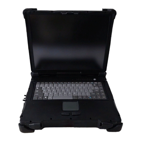
- Page 1 NOTEBOOK COMPUTER RK886EX USER’S GUIDE...
- Page 2 Copyright © 2007 All rights reserved. No part of this publication may be reproduced, transmitted, transcribed, stored in a retrieval system, or translated into any language, or computer language, in any form, or by any means, electronic, mechanical, magnetic, optical, chemical, or other, without the prior written permission of the manufacturer.
- Page 3 ---Consult the dealer or an experienced radio/TV technician for help. Regulatory information / Disclaimers Installation and use of this RK886EX must be in strict accordance with the instructions included in the user documentation provided with the product. Any changes or modifications (including the antennas) made to this device that are not expressly approved by the manufacturer may void the user’s authority to operate...
- Page 4 IMPORTANT NOTE (CO-LOCATION) FCC RF Radiation Exposure Statement: This equipment complies with FCC RF radiation exposure limits set forth for an uncontrolled environment. This device and its antenna must not be co-located or operating in conjunction with any other antenna or transmitter. In order to maintain compliance with the FCC RF exposure guidelines, this equipment should be installed and operated with minimum distance 20cm between the radiator and your body.
- Page 5 European standards dictate maximum radiated transmit power of 100mW EIRP and frequency range 2.400-2.4835GHz. In France, the equipment must be restricted to the 2.4465-2.4835GHz frequency range and must be restricted to indoor use. D=0.0178m is the minimum distance between the EUT and human body to meet the E-field strength of 61V/m UL, TÜV AC Adapter (TÜV includes EN60950 LVD)
- Page 6 Power Conservation This computer consumes much less power than conventional computers; however, power consumption may be reduced by properly configuring the Power Management Setups. It is recommended that the power saving functions be enabled even when not running on battery power. Power Management generally does not degrade system performance while saving power.
-
Page 7: Table Of Contents
CONTENTS GETTING STARTED........................1 ........................... 1 NPACKING ........................2 UICK PERATION ......................3 ONTROLS AND NDICATORS USEFUL INFORMATION ......................7 ............................. 7 OCATION ..........................7 UGGEDNESS ........................7 PERATING YSTEMS AC A ..........................8 DAPTER ............................9 ATTERY POST........................10 P AND .................... - Page 8 ........................24 LOPPY RIVE ........................24 RIVE CD-ROM D ......................... 24 RIVE ........................... 24 OUCH CREEN ........................... 24 PORTS AC A ..........................25 DAPTER ........................25 EHICLE DAPTER ............................ 25 ATTERY ..................26 YSTEM IMENSIONS AND EIGHT ...................... 26 ATERIALS AND ECYCLING ........................
-
Page 9: Getting Started
Getting Started GETTING STARTED Unpacking The following components come with your computer. If anything is missing or damaged please notify the dealer immediately. Computer unit • Removable drive installed on computer (FDD or CD-ROM/DVD) • AC Adapter • AC Power Cord •... -
Page 10: Quick Operation
Getting Started Quick Operation • Loosen the battery screw, remove the battery insulation sheet, and then re- position the battery for operation. • Attach the AC adapter and charge battery for at least 10 minutes. Turn ON the computer by pressing the power switch momentarily. Notice: •... -
Page 11: Controls And Indicators
Getting Started Controls and Indicators Controls and Indicators (Upper) 1. Heater 2. BT/WLAN/GPS 3. Keyboard Scroll Lock 4. Keyboard Number Lock 5. Keyboard Caps Lock 6. HDD in use 7. Secondary Battery Charge 8. Primary Battery Charge 9. Power indicator 10. - Page 12 Getting Started 12. Touch pad 13. Touch pad right button Controls and Indicators (Right) FDD Configuration: 1. FDD in use 2. Diskette eject button CD-ROM Drive Configuration: 1. CD-ROM eject button 2. CD-ROM in use Battery Configuration: (optional) No special control or indicator.
- Page 13 Getting Started eft)-Standard Controls and Indicators (L 1. External Keyboard + PS/2 port 2. LAN Jack 3. IEEE1394 port (Fire Wire) 4. IEEE1394 port 5. USB port (Universal Serial Bus) 6. USB port (Universal Serial Bus) 7. 1x Express and 1x PCMCIA Slots (Option: 2x PCMCIA) 8.
- Page 14 Getting Started Controls and Indicators (Rear) 1. Optional Military connector port 2. Optional Military connector port 3. DC Power Jack 4. External DVI port 5. External RGB Monitor Port 6. Printer/External FDD Port* 7. Docking Port 8. Serial Port COM2 9.
-
Page 15: Useful Information
Useful Information USEFUL INFORMATION Location A clean and moisture-free environment is preferred. Make room for air circulation. Avoid areas with: • Sudden or extreme changes in temperature. • Extreme heat. • Strong electromagnetic fields (near television set, motor rotation area, etc.). •... -
Page 16: Ac Adapter
Useful Information The computer is compatible with most operating systems (OS). However, not all functions are 100% compatible. For example, ACPI, APM, Smart Battery, etc. are not available on DOS, Windows NT, and other non-Microsoft OS. Consequently “Standby”, “Hibernation”, “Battery Gauge” etc. would not work under such operating systems. -
Page 17: Battery
Useful Information The green LED indicates that the AC power is ready. Battery The computer will automatically switch to battery power when the external power source (AC adapter or optional vehicle adapter) is disconnected. Battery Power Saving Tips The computer comes with an intelligent power-saving feature. You may extend the battery life by: •... -
Page 18: Boot Up And Post
Useful Information Note: Battery characteristic varies depending on factors such as ambient temperature, charging method, load current, aging, etc. For example, at low temperature the chemicals of the battery are more inactive, thus decreases the output power. The battery gauge should only be used as a reference. Please do not expect it to show the exact amount of the power remaining. -
Page 19: Standby/Hibernate/Resume
Useful Information The ROM BIOS Power On Self-Test (POST) Each time the computer powers on, it automatically performs a self-test of its memory and hardware devices. Standby/Hibernate/Resume The system can enter standby or hibernate mode by either pressing the power switch or staying idle till timeout. -
Page 20: Rtc
Useful Information CRT+LCD CRT+EFP (no simultaneous LCD+CRT+EFP) Windows setting: Control panel->Intel(R) Extreme Graphics -> select under Device Display resolution of notebook LCD and DVI monitor must be identical Note: Only DVI displays during DOS prompt. After entered Windows both LCD and DVI will display Battery backed up RTC (Real Time Clock/Calendar) is built in an on-board CMOS (Complementary Metal Oxide Semiconductor) chip. - Page 21 Useful Information To re-install the modules: Gently push the module into the slot. Fasten the screw to fix the module.
-
Page 22: Components And Functions
Components and Functions COMPONENTS AND FUNCTIONS Keyboard The keyboard is functionally equivalent to a full size desktop keyboard. A sample key layout is shown below. The Numeric Keypad The numeric keypad functions like an electronic calculator. It is embedded in the main keyboard, with the numeric figures printed on the upper right of their respective keys. -
Page 23: Floppy Disk Drive
Components and Functions Keyboard Backlight (optional) Press [Fn] [F5] key for approximately 1 second turns keyboard backlight ON or OFF. Floppy Disk Drive The computer comes with a 3.5" 1.44MB floppy disk drive (FDD). The 1.44MB FDD can also read and write 720KB double side double density diskette. It is recommended that high density (2HD marking) diskette been used only. -
Page 24: Cd-Rom Drive
Components and Functions Note: NEVER drop your HDD, FDD, CD-ROM module or expose them to high temperature, high humidity, or any hazardous environment. NEVER try to disassemble the module. Static discharge may destroy your device and data. Always pick up the modules by touching the case only. - Page 25 Components and Functions Ports (horizontal version, ports on rear) 1. COM2 2. COM1 3. PS/2 4. USB #1 & #2 5. RGB 6. DVI 7. LAN 8. ANT. 9. DC jack Ports (vertical version, ports on bottom) 1. DVI 2. RGB...
- Page 26 Components and Functions 3. COM2 4. COM1 5. ANT. 6. PS/2 7. DC jack 8. USB Mount the Dockunder: 1. Turn OFF the power. 2. Open the rubber cap of the docking connector. 3. Align the docking connector. 4. Push the computer to join the guiding pins. Do not lift the computer up while docking.
- Page 27 Components and Functions 5. Lock the computer. There are 2 PCI slots on the Dockunder. Maximum card dimensions are 260mm (L: length, including L-bracket thickness) x 115mm (W: width, including gold fingers) x 25 mm (H: height). The total power rating of 2 PCI slots is +5V 3A, +3.3V 3A, +12V 300mA, -12V 300mA.
- Page 28 Components and Functions 12 Touch pad (PS/2 mouse) 13 Co-processor 14 HDD 15 CD-ROM drive COM2 (or Fax/Modem*, IrDA) COM1 (or Touch screen) Free (COM4*) Parallel port 1 *: Optional devices.
-
Page 29: Optional Devices
Optional Devices OPTIONAL DEVICES Memory Card The memory card will expand your memory to facilitate better system performance. The cards are available as following: 512MB,1 GB,2 GB Battery A Lithium Ion rechargeable 2 battery may install into the CD-ROM/FDD compartment. It has the same capacity of primary battery and Smart Battery compliance. -
Page 30: Pcmcia Cover
Optional Devices Resistive touch screens for direct finger touch or pen input instead of mouse or touch pad. PCMCIA Cover Besides the attached PCMCIA rubber cover, there is an optional cover with a metal frame that can be fixed using screws. The cover provides protection from dust or water for cabled PCMCIA cards. -
Page 31: Specifications
Specifications SPECIFICATIONS RK886EX: Intel Core2 Duo (Merom) CPU runs at multiple speeds dependent on CPU type and operating system: The CPU speed switches automatically by detecting AC adapter/battery operation and busy state. Memory System memory Standard: 512MB Expandable:4GB (2GBx 2) -
Page 32: Floppy Disk Drive
Specifications Function: Emulates standard 101/102-key keyboard Floppy Disk Drive Standard: Size: 3.5" Capacity: 1.44MB (formatted) Rotation: 300 RPM Transfer Rate: 500KB/sec Average Access: 94 ms (with settling) Hard Disk Drive Type: 2.5” Interface: Serial ATA CD-ROM Drive Speed: 24 x Interface: (ATAPI) Data transfer rate:... -
Page 33: Ac Adapter
Specifications • External PS/2+Keyboard port • Audio ports (External Speaker/Earphone, Microphone, Line-in) • RJ11 Phone jack for internal Fax/Modem (optional) • RJ45 jack for internal LAN card (optional) • 2 type II or 1 type-III PCMCIA slots • Printer/External FDD port •... -
Page 34: System Unit Dimensions And Weight
Specifications Primary Battery: Type: 9 x 18650 cells Lithium Ion Capacity: 11.1V 6600mAH Dimension: 103 mm(W) x 73 mm(D) x 38 mm(H) Weight: 435 g (0.95 1b.) Battery (optional): Type: 9 x 18650 cells Lithium Ion Capacity: 11.1V 6600mAH Dimension: 150 mm(W) x 90 mm(D) x 20 mm(H) Weight: 560 g (1.2 1b.) -
Page 35: Environmental
Specifications Packing: Carton: Unbleached paper Cushion: Recyclable EPE Carrying bag: Recyclable PE Fiber User's Guide: Recycled/Recyclable paper Please recycle the parts according to local regulations. Environmental Temperature: -20 ~ 50ºC (32 ~ 122ºF) operating -40 ~ 70ºC (-40 ~ 158ºF) storage Humidity: 5~95% Non-condensing operating 95% maximum storage... -
Page 36: Bios Setup
BIOS Setup BIOS SETUP Press [F2] at boot up to enter BIOS setup. Use arrow keys to select options and [+/-] to modify them. When finished, move to ”Exit” and press [Enter] then confirm save by pressing [Y]. Main Menu Phoenix TrustedCore(tm) Setup Utility Main Advanced... -
Page 37: Ide Channel 0 Master Sub-Menu
BIOS Setup Legacy Diskette A Disabled Select floppy type. Note that 1.25 MB 3½” references a 1024 360 Kb " ¼ byte/sector Japanese media 1.2 MB " ¼ format. The 1.25MB, 3½" diskette requires a 3-Mode floppy-disk 720 Kb 3½" drive. -
Page 38: Ide Channel 0 Slave Sub-Menu
BIOS Setup User = you enter parameters of Type User hard-disk drive installed at this Auto connection. Auto = autotypes hard-disk drive CD-ROM installed here. ATAPI CD-ROM = a CD-ROM drive is Removable installed here. ATAPI Removable = removable disk drive is installed here. This setting enables or disables 32 32 Bit I/O Disabled... -
Page 39: Sata Port 0 Sub-Menu
BIOS Setup User = you enter parameters of Type User hard-disk drive installed at this Auto connection. Auto = autotypes hard-disk drive CD-ROM installed here. ATAPI CD-ROM = a CD-ROM drive is Removable installed here. ATAPI Removable = removable disk drive is installed here. This setting enables or disables 32 32 Bit I/O Disabled... -
Page 40: Sata Port 1 Sub-Menu
BIOS Setup User = you enter parameters of Type User hard-disk drive installed at this Auto connection. Auto = autotypes hard-disk drive CD-ROM installed here. ATAPI CD-ROM = a CD-ROM drive is Removable installed here. ATAPI Removable = removable disk drive is installed here. This setting enables or disables 32 32 Bit I/O Disabled... -
Page 41: The General Help Window
BIOS Setup User = you enter parameters of Type User hard-disk drive installed at this Auto connection. Auto = autotypes hard-disk drive CD-ROM installed here. ATAPI CD-ROM = a CD-ROM drive is Removable installed here. ATAPI Removable = removable disk drive is installed here. This setting enables or disables 32 32 Bit I/O Disabled... -
Page 42: Advanced Menu
BIOS Setup Advanced Menu Phoenix TrustedCore(tm) Setup Utility Main Advanced Security TPM State Boot Exit Item Specific Help Legacy USB Support: [Enabled] Summary screen: [Disabled] Display the diagnostic Boot-time Diagnostic Screen: [Enabled] screen during boot QuickBoot Mode: [Enabled] Extended Memory Testing [Just zero it] IGD –... - Page 43 BIOS Setup QuickBoot Mode Disabled Allows the system to skip certain tests while booting. This will Enable decrease the time needed to boot the system. Extended Memory Normal Determines which type of tests Testing will be performed on extended Just zero it memory (above 1M).
-
Page 44: Sio Smc227 Configuration Sub-Menu
BIOS Setup PCI Express – Root Disabled Control the PCI Express Port via Port 1 this setup option. Enable Auto Disabled – Port always disabled. Enabled – Port always enabled. Auto – Only enable if card found. Note that if Root Port 1 is disabled, Root Ports 2-4 will be disabled as well. - Page 45 BIOS Setup COM1 port: [3F8-IRQ 4] Configure COM1 using COM1 mode: [RS232] device options: COM2 port: [2F8-IRQ 3] [Disabled] COM2 mode: [RS232] No configuration COM3 port: [3E8-IRQ 10] COM3 mode: [RS232] [3F8-IRQ 4] COM4 port: [2E8-IRQ 5] Set the base I/O address COM4 mode: [RS232] for COM1...
- Page 46 BIOS Setup COM1 mode RS485 Configure UART mode options: RS422 RS232 [RS485]:External Device TTL1 [RS422]:External Device [RS332]:External Device [TTL1]:Internal Device Configure COM2 using device COM2 port Disabled options: 2F8-IRQ 3 [Disabled] No configuration [2F8-IRQ 3] Set the base I/O address for COM2 COM2 mode RS485...
- Page 47 BIOS Setup Configure COM3 using device COM3 port Disabled options: 3E8-IRQ 10 [Disabled] No configuration [3E8-IRQ 10] Set the base I/O address for COM3 COM3 mode RS485 Configure UART mode options: RS422 RS232 [RS485]:External Device TTL3 [RS422]:External Device [RS232]:External Device [TTL3]:Internal Device Configure COM4 using device COM4 port...
- Page 48 BIOS Setup COM4 mode RS485 Configure UART mode options: RS422 RS232 [RS485]:External Device TTL4 [RS422]:External Device [RS232]:External Device [TTL4]:Internal Device Configure Printer1 device options: Printer1 Disabled 378-IRQ 4 [Disabled] No configuration [378-IRQ 7] Set the base I/O address for Printer1 Printer1 mode Standard Configure Printer1 mode options:...
-
Page 49: Security Menu
BIOS Setup Security Menu Warning: If you forget user/supervisor password, the computer has to send back to manufacturer and replace EEPROM to make it work again. Phoenix TrustedCore(tm) Setup Utility Main Advanced Security TPM State Boot Exit Item Specific Help Processor Serial Number [Disabled] Fixed disk boot sector:... - Page 50 BIOS Setup Diskette access Supervisor Control access to diskette drives User USB Interface Disabled Control the listed USB Functions by setting the item to the desired Enabled value. AC97 Audio Interface Disabled Control Detection of the AC97 Audio Device. Auto Auto = AC97 Audio will be enabled if present, disabled otherwise.
-
Page 51: For Most Frequently Altered Setup "Rf Security Control " Please Refer Following :43
BIOS Setup For most frequently altered setup “RF Security Control” please refer following: RF Security Control Sub-Menu Phoenix TrustedCore(tm) Setup Utility Security RF Security Control: Item Specific Help Wireless Lan Control Wireless Lan: [Disabled] Help Select Item –/+ Change Values Setup Defaults ↑↓... -
Page 52: Tpm State Menu
BIOS Setup TPM State Menu Phoenix TrustedCore(tm) Setup Utility Main Advanced Security TPM State Boot Exit Item Specific Help Current TPM State: Enabled and Deactivated Change TPM State: [No Change] Change TPM State Help Select Item –/+ Change Values Setup Defaults ↑↓... - Page 53 BIOS Setup Keys used to view or configure devices: Up and Down arrows select a device. <+> and <–> moves the device up or down . <f> and <r> specifies the device fixed or removable . <x> exclude or include the device to boot .
-
Page 54: Exit Menu
BIOS Setup Exit Menu Phoenix TrustedCore(tm) Setup Utility Main Advance Security TPM State Boot Exit Item Specific Help Exit Saving Changes Exit Discarding Changes Load Setup Defaults Exit System Setup and save Discard Changes your changes to CMOS. Save Changes Help Select Item –/+... -
Page 55: Utilities And Drivers
Utilities and Drivers UTILITIES AND DRIVERS Note: Most device drivers are available in Windows 2000/XP. Only when the default driver does not work properly you need to install the factory bundled drivers. The utility CD includes most drivers of the computer’s installed devices. Consult dealer if any driver is missing. -
Page 56: Audio Driver
Utilities and Drivers 1280x 1024x 24-bit color 1280x 1024x 32-bit color 1600x 1200x 16-bit color 1600x 1200x 24-bit color 1600x 1200x 32-bit color 2048x 1536x 16-bit color 2048x 1536x 24-bit color 2048x 1536x 32-bit color By Panning. The table lists typical display modes only. The system also supports standard video modes with lower resolution and color. -
Page 57: Cd-Rom Driver
Utilities and Drivers Then cancel the prompt of installation wizard to setup the driver from the CD (\RK8EX\Driver\Touchscreen\DP9000\DMC9000 Windows 2000-XP- 2003\setup) then follow the prompt to complete installation and restart. CD-ROM Driver In Windows 2000/XP, you don’t need to install drivers, because it is included in the drivers list. -
Page 58: Wireless Manager
Utilities and Drivers Wireless Manager For flight safety and power saving reason, there is a utility provided easily to enable/disable RF devices of Wireless Lan/GPRS/GPS/Bluetooth in the run time Insert the Driver CD into the CD-ROM. Click setup.exe in the directory of Utilities\WirelessManager then follow the prompt to complete installation. -
Page 59: Maintenance / Service
MAINTENANCE / SERVICE Cleaning ALWAYS turn OFF the power, unplug the power cord and remove the battery before cleaning. The exterior of the system and display may be wiped with a clean, soft, and lint-free cloth. If there is difficulty removing dirt, apply non-ammonia, non-alcohol based glass cleaner to the cloth and wipe. - Page 60 for your records) Name • Address • Unit serial number • Place and date of purchase or the original invoice number • Date of failure • A DETAILED Description of the problems you have encountered • A list of the hardware/software configuration, if applicable. •...
Need help?
Do you have a question about the RK886EX and is the answer not in the manual?
Questions and answers