Table of Contents
Advertisement
Advertisement
Table of Contents

Related Manuals for Bryston 6B SST


Summary of Contents for Bryston 6B SST
- Page 1 POWER AMPLIFIER OWNER’S MANUAL...
-
Page 2: Table Of Contents
Table of Contents General Introduction Instalation and Ventilation Rear Panel Input Settings/Connections Setting Input Selector Switch Balance Input Connector Configuration Setting Polarity Setting Input Sensitivity Output Binding Posts and Polarity Front Panel Description LED Indicators (Power-up Sequence) LED Indicators (Operating Conditions) Power Control Panel Master Curcuit -Breaker AC Power Input Local/Auto Switch Local/External Switch Rack Mounting Instructions Individual Module Removal Channel Fuse Type/Location 5.1 Typical Home Theatre Setup Block Diagram of the 6BSST Typical Performance Graphs Technical Specifications... -
Page 3: General Introduction
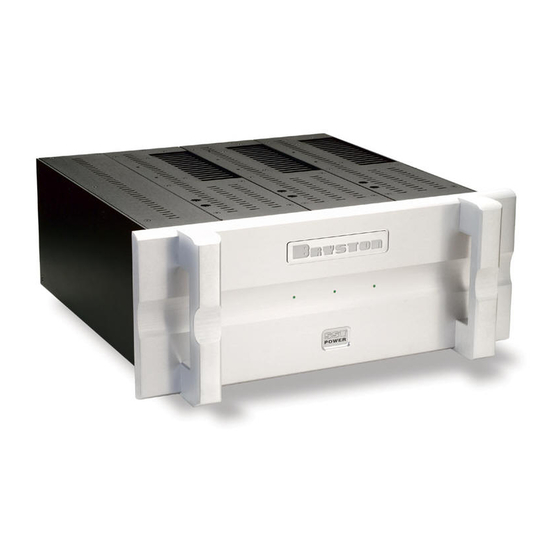
6BSST THREE CHANNEL POWER AMPLIFIER Introduction Thank you for choosing the 6BSST Three Channel Power Amplifier. Bryston welcomes any suggestions you may have, or comments regarding the operation of your amplifier. We consider you, our customer, to be Bryston’s most important resource, and your opinion is very much appreciated. Description The 6BSST is a modular design 3 x 300W per channel audio power amplifier. Each channel selects a balanced or single ended input. Each channel selects a gain of 29dB(1v), 23dB(2v) or 17dB(4v). Each channel input may be operated invert- ed or non-inverted operation(0 or -180 degrees). The power up of the 6BSST may be controlled by remote control voltage. The 6BSST includes ‘soft start’ power control circuitry to eliminate high inrush currents when A/C power is applied. Warranty ( see back page for details ) Shipping Box & Packing Material Please keep the original shipping box and all packing material. This will ensure the amplifier is protected in future transport. In the unlikely event you have a problem and must return it for service you must use the proper packing material. Ship the amplifier only in the original packing material, as the unit is not insurable by carriers otherwise. Installation ( see rack mounting section if applicable ) Ventilation. The most important installation consideration is ventilation. The 6BSST is a convection-cooled amplifier. -
Page 4: Input Select Switch
1. Input Select Switch. Each 6BSST channel gives the user the option of switching between either balanced input or single ended input. 2. Balanced Input connector. ( Imp. 20k ) This input connector accepts standard ‘XLR’ or 1/4” TRS . Use quality, 100% shielded cables with gold plated connectors. ‘TRS’ type ‘RCA’ type 3. Single Ended Input. ( Un-balanced input ) ( Imp. 50k ) This input connector accepts standard ‘RCA’ or ‘Phono’ connectors. Use quality, 100% shielded cables with gold plated connectors. Balanced input Vs Single ended input: The balanced input requires a balanced pre-amp source. Balanced systems provide noise protection from external electrical interference, so cable length can be very long (50m or longer ). -
Page 5: Output Binding Posts And Polarity
6. Output binding posts & polarity. The RED binding post is connected to the amplifier output. Connect to this post the (+) terminal on the loudspeaker. The BLACK binding post is connected to signal ground. Connect to this post the (-) terminal on the loudspeaker. When the polarity switch is set for 0 degrees (normal operation ) the output at the RED binding post is in phase with the input signal. When the polarity switch is set for 180 degrees (inverted operation) the the output at the RED binding post is 180 degrees out of phase with the input signal. The Output binding posts provide three different interconnect options. Combinations may be used when bi-wiring. See fig- ure 2 below. Cables should be kept as short as practical and should never be terminated with connectors that may become confused for AC power connectors. Cables should be dressed away from input and power cables. 1. Banana plugs offer a quick disconnect option. Before inserting a banana plug into the binding post be sure to tighten the post nut to avoid rattling and to provide full insertion of the banana plug. Gold plated locking banana plugs are available from Bryston. 2. Spade lugs provide high contact area and secure fastening. Lugs should be gold plated. See diagram for details. Post diameter is 5/16’ ( 8mm ),lug width 5/8” (16 mm). Gold plated spade lugs are available from Bryston. 3. Stripped bare wire up to 3 gauge can be inserted through the hole in the binding post and held in place by tightening the post knob. Additional tightening pressure can be achieved using a coin in the slots of the knob. Do not over tighten or the binding post may become damaged. Note that copper wire is malleable and may require further tightening after the initial installation. Fig 2 Spade lug dimensions Coin 7. Rear Handle (Page 2 Fig 1) The handle on each channel is to protect the connectors and removal of the channel from the chassis. -
Page 6: Front Panel Description
Front Panel 1. 'SST POWER' switch The front panel label 'SST POWER', is a touch sensitive membrane switch used to apply or remove a/c line power to the 6BSST circuitry. Push firmly the center of the switch until the power-up sequence begins. Push again and the 6BSST will power-down. ( Note: the rear circuit breaker must be on for the 6BSST to power-up) 2. LED Indicators Each 6BSST channel has a LED indicator to monitor the following channel conditions: indicates channel has no power. nlit indicates channel is muted (power-up-down sequence) - i ndicates channel operation is normal. Reen - indicates channel clipping. lashinG indicates channel thermal shutdown. RanGe Power up sequence After pushing the 'SST POWER' switch, each channel led will turn from unlit to red (mute). When the power supplies have stabilized the channel will come out of mute and the led will change to green (normal operation). Unlit led ( No power ) The 6BSST channel led when unlit indicates no A/C mains power is present at the channel. If all channel led indicators are unlit the 6BSST probably needs only to be powered on. A single led not lighting possibly indicates blown channel fuses. When checking fuses switch off the circuit breaker on the rear panel, or unplug the power cord. Use only the specified quick-acting 4 amp 250V 5mm x 20mm fuses. See page 6 for the fuse locations. Clipping ( flashing red ) Clipping occurs when the channel output level no longer can follow the level increase at the input (Over driven outeeput condition). When a 6BSST channel is driven into clipping the channel led will change from green to red then back to... -
Page 7: Power Control Panel
6BSST THREE CHANNEL POWER AMPLIFIER Power Control Panel 1. Master circuit - breaker. The 6BSST uses a magnetic-trip circuit breaker (1) to protect the amplifier. This switch should be ‘OFF’ when installing the 6BSST. When switched ‘OFF’ all A/C power is removed from the amplifier, including standby power. The circuit breaker is not the day to day power switch and should be switched and left ‘ON’ after the installation is complete.Use the ‘SST POWER” switch or an exter- nal control voltage to Power-up or Power-down the amplifier. Should the breaker trip, lower or remove the amplifier input signals. Switch the breaker to the ‘ON’ position. Then power the unit up normally. The circuit breaker must be ‘ON’ at all times for the 6BSST to operate. 2. -
Page 8: Rack Mounting Instructions
The 6BSST 19” version may be rack mounted with or without the ability to remove the channels. If removal of the chan- nels is desired then the shipping screws securing the channels need to be removed. REMOVE 4 6-32 SCREWS FROM THIS SIDE FUSES - USE SAME TYPE ONLY FAST ACTING 4A 250V 5mm X 20mm DO NOT REMOVE SCREWS FROM RACK MOUNT BRACKET Rack Mounting Instructions TOP VIEW REMOVE 8 SCREWS 632 X 3/8” BOTTOM VIEW 6BSST THREE CHANNEL POWER AMPLIFIER REMOVE 3... -
Page 9: Typical Home Theatre Setup
6BSST THREE CHANNEL POWER AMPLIFIER Typical 5.1 Home Theatre Setup Left Front Right Front 6BSST 3 x 300w per ch Powered Subwoofer Center Home Theatre processor Left Rear Right Rear 4BSST 2 x 300w per ch. -
Page 10: Block Diagram Of The 6Bsst
6BSST THREE CHANNEL POWER AMPLIFIER... -
Page 11: Typical Performance Graphs
6BSST THREE CHANNEL POWER AMPLIFIER Typical Band-pass Noise Power supply artifacts are all below -95 dBu balanced input with 23dB gain shown dBu: dB relative to a reference of 0.7746 Volts Typical THD+N Harmonic Content The harmonic content of the 6BSST is all even order. - Page 12 6BSST THREE CHANNEL POWER AMPLIFIER Typical Frequency Response 8 ohm 300w<.01dB 20Khz. 4 ohm 500w<.1dB 20Khz. Typical Phase Response 4 ohm 600w 8 ohm 300w...
- Page 13 6BSST THREE CHANNEL POWER AMPLIFIER Typical THD+N Sweep Graph shows that distortion is essentially unaffected by load. 4v balanced input shown. 4 ohm 600w 8 ohm 300w Typical IMD Sweep 4 ohm 600w 8 ohm 300w...
-
Page 14: Typical Crosstalk
6BSST THREE CHANNEL POWER AMPLIFIER Damping Factor 8 ohm reference Typical Crosstalk channel 2 reading with channels 1 & 3 driven to 300w into 8 ohms channel 2 reading with channels 1 & 3 driven to 600w into 4 ohms... -
Page 15: Technical Specifications
Power Output, 29dB - 1.7Vin = 300W @ 8 Ohms - (1V Position) Gain Select and Sensitivity 23dB - 3.4Vin = 300W @ 8 Ohms - (2V Position) 17dB - 6.8Vin = 300W @ 8 Ohms - (4V Position) Input Impedance 50 Kohms single ended 20 Kohms balanced Distortion < 0.005% 20Hz to 20kHz at 300 watts into 8 ohms, IM or THD+noise < 0.007% 20Hz to 20kHz at 500 watts into 4 ohms Noise Measured with input shorted - 20Hz to 20kHz. >112dB below rated output 29dB gain (- 75dBu) >115dB below rated output 23dB gain (- 78dBu) >118dB below rated output 17dB gain (- 81dBu) Slew Rate >60 volts per microsecond Power Bandwidth <1 Hz to over 100 kHz Damping Factor Over 500 at 20 Hz, ref. 8 ohms Dimensions Rack mount version 48.3 x 13.3 x 39.4cm - 19” x 7” x 20.5“ with handles - mounted rack depth - 46.7cm - 18.375" 17” version 43.2 x 13.3 x 39.4cm - 17” x 7” x 19“ Weight: approx. 36kg - 80 lbs Power Consumption &Heat Load single channel 300W @ 8 ohms -... -
Page 16: Important Safety Instructions
Bryston authorized dealer to qualify for warranty service. The warranty is transferable from the original owner to a subsequent owner as long as a copy of the bill-of-sale from the original authorized Bryston dealer accompanies the re-sale. The copy of the bill of sale to any subsequent owner need ONLY include the Name of the Bryston Authorized Dealer and the Model and Serial number of the Bryston product The warranty will only be honored in the country of the original purchase unless otherwise pre-authorized by Bryston.
Need help?
Do you have a question about the 6B SST and is the answer not in the manual?
Questions and answers