Table of Contents
Advertisement
Quick Links
Advertisement
Table of Contents

Summary of Contents for Bryston 6BSST
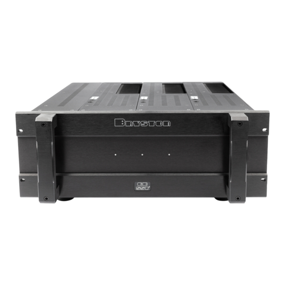
- Page 1 BRYSTON OWNER’S MANUAL Instructions For Bryston SST Series Amplifiers Model 6BSST...
-
Page 2: Table Of Contents
AC Power Input Local/Auto Switch Local/External Switch Rack Mounting Instructions Individual Module Removal Channel Fuse Type/Location 5.1 Typical Home Theatre Setup Block Diagram of the 6BSST Typical Performance Graphs Technical Specifications Important Warranty Information 6BSST THREE CHANNEL POWER AMPLIFIER Page 1... -
Page 3: General Introduction
Before plugging in the power cord be sure your 6BSST is specified for the correct a/c voltage for your locality. The volt- age is listed to the right of the power input connector. The circuit feeding the 6BSST should be sufficient so as not to cause the circuit breaker to trip. -
Page 4: Rear Panel Input Settings/Connections
1. Input Select Switch. Each 6BSST channel gives the user the option of switching between either balanced input or single ended input. 2. Balanced Input connector. ( Imp. 20k ) This input connector accepts standard ‘XLR’ or 1/4” TRS . -
Page 5: Output Binding Posts And Polarity
The handle on each channel is to protect the connectors and removal of the channel from the chassis. This handle should never be used to carry the 6BSST. Use only the front panel handles for carrying the 6BSST, or lift from the sides of the chassis if not equipped with front panel handles. -
Page 6: Front Panel Description
Unlit led ( No power ) The 6BSST channel led when unlit indicates no A/C mains power is present at the channel. If all channel led indicators are unlit the 6BSST probably needs only to be powered on. A single led not lighting possibly indicates blown channel fuses. -
Page 7: Power Control Panel
Supply a 4v to 12v A/C or DC control voltage to the ‘IN’ terminals of connector ( 5 ). Use paired wire of 22 gauge to 18 gauge sufficient in length between the source device and the 6BSST. (see ‘W’ ) Select switch (4) to “External”. -
Page 8: Rack Mounting Instructions
The 6BSST 19” version may be rack mounted with or without the ability to remove the channels. If removal of the chan- nels is desired then the shipping screws securing the channels need to be removed. REMOVE 4 6-32 SCREWS... -
Page 9: Typical Home Theatre Setup
Typical 5.1 Home Theatre Setup Left Front PUSH Powered Subwoofer Left Rear CAUTION PRECAUTION 6BSST 6BSST 3 x 300w per ch PUSH RIGHT CENTER LEFT UNBALANCED OUTPUTS RIGHT LEFT CENTER RSURR LSURR BRYSTON L T D / L T E E... -
Page 10: Block Diagram Of The 6Bsst
6BSST THREE CHANNEL POWER AMPLIFIER... -
Page 11: Typical Performance Graphs
Typical Band-pass Noise Power supply artifacts are all below -95 dBu balanced input with 23dB gain shown dBu: dB relative to a reference of 0.7746 Volts Typical THD+N Harmonic Content The harmonic content of the 6BSST is all even order. - Page 12 6BSST THREE CHANNEL POWER AMPLIFIER Typical Frequency Response 8 ohm 300w<.01dB 20Khz. 4 ohm 500w<.1dB 20Khz. Typical Phase Response 4 ohm 600w 8 ohm 300w...
- Page 13 6BSST Typical THD+N Sweep Graph shows that distortion is essentially unaffected by load. 4v balanced input shown. 4 ohm 600w Typical IMD Sweep 4 ohm 600w THREE CHANNEL POWER AMPLIFIER 8 ohm 300w 8 ohm 300w...
- Page 14 6BSST THREE CHANNEL POWER AMPLIFIER Damping Factor 8 ohm reference Typical Crosstalk channel 2 reading with channels 1 & 3 driven to 300w into 8 ohms channel 2 reading with channels 1 & 3 driven to 600w into 4 ohms...
-
Page 15: Technical Specifications
3 channels @ 300W @ 8 ohms - Max. Heat Dissipation 8 ohms - single channel 500W @ 4 ohms - 3 channels @ 500W @ 4 ohms - Max. Heat Dissipation 4 ohms - 6BSST Technical Specifications At Idle - THREE CHANNEL POWER AMPLIFIER 625 Watts 2100 Watts 4100 Btu/Hr. - Page 16 Bryston. In the event of a defect or malfunction, Bryston will remedy the problem by repair or replacement, as we deem necessary, to restore the product to full performance.


Need help?
Do you have a question about the 6BSST and is the answer not in the manual?
Questions and answers