Table of Contents
Advertisement
Quick Links
Advertisement
Table of Contents

Summary of Contents for Security Tronix ST-DVR8716BG
- Page 1 USER MANUAL ST-DVR8716BG 16-Channel Digital Video Recorder v2.0 11/8/11...
-
Page 2: Table Of Contents
TABLE OF CONTENTS PACKAGE C ONTENTS....................4 PRODUCT D ESCRIPTION ....................4 SPECIFICATIONS ......................5 INSTALLATION ......................6 UNPACKING and HANDLING ......................... 6 MECHANICAL INSPECTION ........................6 SPECIAL ATTENTION..........................6 WIRING CONNECTIONS and HARD DRIVE INSTALLATION.......... - Page 3 Auto Pan, Flip and Reset ..........................40 Other PTZ Control Functions .........................40 SYSTEM SETTINGS..........................41 General Settings..............................41 Encode Settings..............................43 Network Settings ..............................43 Network Service Settings ..........................45 GUI Display Settings............................50 PTZ Configuration Settings..........................50 ...
-
Page 4: Ontents
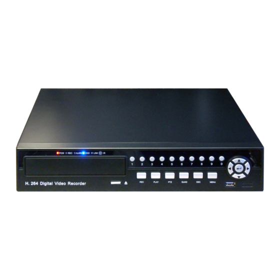
One CD with manufacturer documentation and remote management software PRODUCT DESCRIPTION The ST-DVR8716BG is a cost-effective DVR designed for the security professional as a digital surveillance product. Based on an embedded LINUX operating system the ST-DVR8716BG provides a very stable platform featuring standard H.264mp video compression and G.711A audio compression to ensure high quality imaging, low error coding ratio and single frame playback. -
Page 5: Specifications
SPECIFICATIONS ST-DVR8716BG Specifications (Typical) 1. Compression H.264 2. Video Signal NTSC 3. Video Input 16 BNC Female 4. Video Output 1 VGA, 1 BNC 5. Audio Input 1 RCA Female 6. Audio Output 1 RCA Female 7. Record CIF/QIF 8. Recording Modes Manual, Alarm, Motion Detect, Schedule 9. -
Page 6: Installation
INSTALLATION This symbol is intended to alert the user to the presence of important operating and maintenance (servicing) instructions. This symbol is intended to alert the user to the presence of uninsulated “dangerous voltage” within the product’s enclosure that may be of sufficient magnitude to constitute a risk of electrical shock. -
Page 7: Wiring Connections And Hard Drive Installation
4. WIRING CONNECTIONS and HARD DRIVE INSTALLATION Item Keypad Key Description CAM1 – CAM16 Video In BNC ports for cameras 1 through 16 MON OUT Video Out BNC port for connection to a monitor A-IN Audio In RCA port A-OUT Audio Out RCA port USB Ports USB port for mouse and back up drive or flash drive... -
Page 8: Hard Drive (Hdd) Installation
mount using the four included screws. Connect the drive to the unit using one of the SATA hard drive cables. Then connect the hard drive to the drive’s power connector. Once the drive is installed secure the case. When applying power to the DVR the unit should automatically (i) detect the drive, (ii) alert the user to confirm initialization, and (iIi) begin to initialize it. -
Page 9: Hdd Storage Calculator
HDD Storage Calculator Selecting the appropriate size hard disk drive is dependent upon a number of variables including: Recording Mode: CIF, QCIF Recording Quality Number of Cameras Frames per Second Hours per Day to Record Securitytronix provides a DVR Hard Disk Drive Storage Calculator to help determine the number of days of recording are possible based upon HDD capacity. - Page 10 Type: JRC-27F Interface Material Silver Resistance Load Rating Switch Capacity 30VDC @2A, 125VAC @1A Maximum Switch Power 125VAC, 160W Maximum Switch Voltage 250VAC, 120VDC Maximum Switch Current Isolation Contact to Contact 1000VAC for 1 minute Contact to Coil 1000VAC for 1 minute Interface and Winding 1000VAC for 1 minute Surge Voltage...
-
Page 11: Controls
CONTROLS 1. FRONT PANEL CONTROLS Item Panel Key/Indicator Description Power indicator light Record indicator light ALARM Alarm indicator light Hard disk drive activity light LINK Indicates that the DVR is being remotely accessed Infrared remote receiver 1 – 0 Numeric keys; select channel display window ... -
Page 12: Infrared Remote
2. INFRARED REMOTE Keypad Key Description POWER Power DVR On/Off Record button; Display the Record Mode window SWITCH Switch from 1, 4, 8, 9 and 16-window monitor display Slow video playback Fast video playback Stop video playback II... -
Page 13: Mouse Control
3. MOUSE CONTROL Plug the optical mouse into a USB port on the DVR’s real panel. The DVR’s optical mouse operates in the same manner as the typical computer mouse. The information below identifies key mouse control functions using the mouse left and right keys. Left Mouse Key –... -
Page 14: Operation
OPERATION 1. POWERING ON and SHUTTING DOWN Powering On a. Plug the included power supply into the DVR’s power port and into an appropriate AC power outlet. b. Once there is power to the DVR, POWER indicator light will be displayed on the DVR’s front panel. -
Page 15: Accessing System Menu
If the DVR is recording (normal recording, time recording or alarm recording) at the time the unit is turned off the DVR will automatically save the recording before shutting down. When the DVR is powered back on it will automatically revert to that recording condition prior to it being turned off. 2. -
Page 16: Preview Mode
4. PREVIEW MODE Once logged into the system the DVR enters the Preview Mode. The Preview Mode displays current monitoring activity in a single or multiple windows. The user may right click the mouse to switch between preview windows. The date, time, channel name and channel status are displayed. - Page 17 Advanced When moving the mouse cursor to any of the above GUI’s icons, a brief description of that menu function is displayed. Each menu option (as represented by an icon) may have multiple functions in sub-menus. It is important to remember that when making a menu or sub-menu setting, the user must SAVE or CONFIRM that setting prior to exiting the menu or sub-menu.
-
Page 18: Recording Operation
PTZ Config Configure PTZ cameras per channel Tour Set sequential screen display by single or multiple windows Hard disk status and configuration settings Management User Account Set and modify user accounts, permissions and passwords Management Online User Sever connection between an online user and the DVR Output Adjust Adjust monitor display borders Automatic... -
Page 19: Auto Recording
Manual – Under manual recording the DVR records regardless of any condition. Recording begins once a channel is selected under Manual and confirmation is made. Stop – All recording (manual or schedule) will cease or not begin once the channel is selected and confirmation is made. -
Page 20: Auto Recording - Motion Detection Recording
d. PRERECORD – If desired, the DVR can record from 1 to 30 seconds before an event happens. The time length is determined by the code stream. e. RECORD MODE – Set the recording condition: scheduled, manual or stop. WEEK and PERIODS – Select the day and time slot the camera and DVR are to perform the recording function. - Page 21 e. REGION – The viewable area where the camera is to detect motion and the DVR is to record. By setting a region it is possible to reduce intermittent and/or low priority events that could trigger motion detection (e.g., a ceiling fan, a breeze moving curtains).
- Page 22 g. INTERVAL – Set an interval period in seconds. If there are several motion detection signals occurring within the interval period only one alarm signal is turned on. h. ALARM OUTPUT – If an external signal (e.g., bell) to be activated upon a motion detection event highlight the checkbox.
-
Page 23: Auto Recording - Video Blind
Auto Recording – Video Blind When the video image is lost, such as the camera being covered, the Video Blind function can be turned on and linked to an alarm function. a. Go to Main Menu, click on the Alarm icon and then the Video Blind icon. A Video Blind setup screen similar to the one below will appear. -
Page 24: Auto Recording - Video Loss
PTZ ACTIVATION – In the event of a video blind or other alarm a PTZ camera can be activated and set to automatically pan and or cruise among pre-determined spots. By clicking on SET a PTZ Activation screen appears. For each PTZ camera select the type of PTZ function desired from the drop-down menu. When done, click OK. - Page 25 d. PERIOD – To set the day and time period for the video loss to take place click SET and a Set Screen appears. Select the desired day from the drop-down menu or ALL for the entire week. Four possible time slots are available for each day. Use the mouse and soft keyboard to enter the required time periods.
-
Page 26: Auto Recording - Alarm Recording
Auto Recording – Alarm Recording The first step to setting up alarm recording is to configure the DVR’s Alarm Output. a. From Main Menu click the Alarm icon followed by the Alarm Output icon. Alternatively, click the right mouse button to display the Short-cut Menu and select Alarm Output. An Alarm Output screen similar to the one below will be displayed. - Page 27 d. ALARM IN – Select the alarm input from the drop-down menu. e. ENABLE – Highlight the checkbox if the Alarm Input is to be enabled. TYPE – From the drop-down menu select whether the alarm is Normal Open or Normal Close.
-
Page 28: Playback Operation
7. PLAYBACK OPERATION a. Playback is accessed in one of three ways: (i) by clicking the right mouse button to display the Short-cut Menu and selecting PlayBack, (ii) by going to Main Menu, clicking the Record icon then clicking the PlayBack icon, or (iii) pressing the Play/Pause button on the DVR’s front panel. - Page 29 FILE TYPE – Six file types are available selectable from the drop-down menu. Then using the adjacent drop-down menu select from where the file is located: on the DVR’s hard disk configured for Read/Write or from a Backup Device ...
-
Page 30: Backing Up Recording Files
8. BACKING UP RECORDING FILES Recording files can be backed up using USB storage devices (e.g., USB flash drive, USB CD-R/RW, USB DVD-R/RW) or a LAN for storage. Note that if a DVD burner is installed, a USB flash drive cannot be used for backup. There are two methods for backing up files: (i) through the PlayBack/File Search screen or (ii) by going through Main Menu, clicking on the Record icon followed by the Backup icon. -
Page 31: File Backup - Direct From Main Menu
g. Click the START button. Backup will begin and the screen will display backup progress. When the backup is completed click the dialog box’s OK button. File Backup – Direct From Main Menu a. From Main Menu click the Record icon followed by the Backup icon. A Record/Backup screen similar to the one below will appear. -
Page 32: Ptz Control
backup drive. STOP aborts the backup process. BURN CD formats the a CD / DVD in the optional CD / DVD-RW drive. c. Click the BACKUP button. Doing so will display a Backup screen similar to the one below. Perform a file search using the search criteria (Type, Channel, Start Time and End Time) in the Backup screen then click ADD. -
Page 33: Ptz Camera Configuration
b. Connect the PTZ camera’s video cable to the DVR’s video input port. c. Power the PTZ camera after all connections are made. PTZ Camera Configuration Setting up the PTZ camera for DVR control is done by the following steps: a. -
Page 34: Ptz Camera Control
PTZ Camera Control To access the PTZ control functions click the right mouse button to display the pop-up Short-cut Menu and select PTZ CONTROL or press the PTZ button on the DVR’s front panel. Upon doing so a PTZ Control interface similar to the one below will appear. a. - Page 35 b. Click the SET button on the PTZ Control interface. A screen similar to the one below will appear. c. Highlight PRESET and enter the preset number using the left mouse button and soft keyboard. d. Clicking the SET button on the above screen will return to the PTZ Control interface. e.
-
Page 36: Tour Between Points
Tour Between Points Multiple preset points can be connected to create “tour lines”. The PTZ camera can be programmed to cruise a set of presets along a specified line. a. Using the direction control buttons move the camera to a desired point. b. -
Page 37: Pattern
Using the left mouse button and soft keyboard enter the desired tour number to be called. Click the TOUR button and the camera will travel along the tour line’s preset points. Pattern A PTZ camera can be controlled to repeatedly scan tour lines. a. -
Page 38: Border Scan
To call a pattern, from the PTZ Control interface screen click the PAGE SWITCH button once to display a page for calling presets, patterns, tours, and scans. The control page displayed will be similar to the one below. g. Using the left mouse button and soft keyboard enter the desired pattern number to be called. - Page 39 c. Click the LEFT button. Doing so will return to the PTZ Control interface screen where the direction buttons will be used to position the camera at the desired right boundary point. Once done, press the SET button. d. Click the RIGHT button. e.
-
Page 40: Auto Pan, Flip And Reset
Auto Pan, Flip and Reset a. From the PTZ Control interface screen click the PAGE SWITCH button. A screen similar to the one below will be displayed. b. For automatic horizontal camera rotation click the AUTOPAN button. c. For automatic vertical camera rotation click the FLIP button. d. -
Page 41: System Settings
a. DIRECT AUX OPER – From the drop-down menu select the auxiliary equipment (e.g., a light) and click on ON or CLOSE to control. b. AUX NUM OPER – The operation of the corresponding auxiliary switch according to the PTZ agreement. 10. - Page 42 Highlight the ENABLE checkbox and complete the DST START and END settings. Click OK when finished. c. DATE FORMAT – From the drop-down menu select the desired format: year, month, date; month, date, year; date month, year. d. DATE SEPARATOR – From the drop-down menu select the date separator. Options are . −...
-
Page 43: Encode Settings
Encode Settings From the Main Menu click the System icon then the Encode icon. An Encode settings screen similar to the one below will be displayed. Note the second column of pull down menu options beginning with “Extra Stream” consists of settings for mobile phone access. If “video” is not checked below the column mobile monitoring will not be possible. - Page 44 From Main Menu click the System icon then the Network icon. A Network settings screen similar to the one below will be displayed. a. NET CARD – Wire Netcard is the fixed option. b. DHCP ENABLE – Highlight the checkbox if the IP address is automatically obtained. a.
-
Page 45: Network Service Settings
Network Service Settings From the Main Menu click the System icon followed by the NetService icon. A NetService settings screen similar to the one below will be displayed. a. Choose the network service option by highlighting it with the mouse or front panel UP/DOWN buttons. - Page 46 SERVER IP – Use the mouse cursor, left mouse button and soft keypad to input the IP address for the installed NTP server. PORT – Default is 123. The port can be set according to the NTP server. ...
- Page 47 NEED SSL – Highlight the checkbox if the Secure Socket Layer protocol is required. USER NAME – Enter the email server user name. PASSWORD – Enter the email user’s password. SENDER – Set the email sender address. ...
- Page 48 DOMAIN NAME – Input the domain name registered by DDNS. USER NAME – Input the account registered by DDNS. PASSWORD – Input the password registered by DDNS. g. FTP – FTP is available only when an alarm takes place. If FTP is enabled the related alarm event record and snapshot picture are uploaded to a FTP server.
- Page 49 h. MOBILE – The DVR can be configured to support smartphone access and management. . Note a compatible remote client must be installed on the smartphone and a router must direct the smartphone client to the mobile port. A Mobile configuration screen similar to the one below will be displayed.
-
Page 50: Gui Display Settings
GUI Display Settings The DVR’s GUI can be set to a number of configurations for displaying channel name, channel title, time, alarm status, recording status and other information in Preview mode, Video File mode and remote access mode. From Main Menu click the System icon then the GUI Display icon. A GUI Display setting screen similar to the one below will appear. -
Page 51: Tour (Screen Sequencing) Settings
Tour (Screen Sequencing) Settings Each channel window can be displayed as a single window, one of four windows, one of nine windows or one of sixteen windows. Further, by highlighting the ENABLE TOUR checkbox each channel window can be sequenced according to a desired time interval. From Main Menu click the System icon followed by the Tour icon. -
Page 52: Advanced Features
11. ADVANCED FEATURES HDD Management From Main Menu click the Advanced icon followed by the Hard Disk Management icon. The HDD Manage settings screen similar to the one below will appear. The screen displays current hard drive information including disk number, input port, type, status and drive capacity. -
Page 53: User Account Management
User Account Management Users can be added to and deleted from the system. Further, user privileges, permissions and passwords can be modified. From Main Menu click the Advanced icon followed by the User Account Management icon. The Account settings screen similar to the one below will appear. The maximum User Name length is 8 characters. - Page 54 e. ADD GROUP – Clicking this button displays the Add Group screen where the group name is created and group permissions are set. DELETE USER – Clicking this button deletes a user once a confirmation is made. g. DELETE GROUP – Clicking this button displays a Delete Group screen for removing a particular group.
-
Page 55: Online User
Online User Information on those users accessing the DVR through the network is displayed. Individual users can be disconnected from the DVR and locked out until the DVR’s next reboot or change the user’s permissions. From Main Menu click the Advanced icon followed by the Online User icon. An Online User screen similar to the one below will be displayed. -
Page 56: Auto Maintain
Auto Maintain Using the drop-down menus the DVR can be configured to automatically reboot and/or automatically delete old files. From Main Menu click the Advanced icon followed by the AutoMaintain icon. The displayed AutoMaintain screen is similar to the one below. Restore Defaults To restore the DVR settings to the factory defaults from Main Menu click the Advanced icon followed by the Restore icon. -
Page 57: Upgrade
To select the desired settings for restoring to the factory defaults highlight the appropriate checkbox. Upgrade From time-to-time the factory will provide upgrades to the DVR’s system software. Securitytronix will announce any upgrades and the upgraded software will be downloaded from a Securitytronix site to a USB device (e.g., flash drive). -
Page 58: Device Information
Device Information From Main Menu click the Advanced icon followed by the Device info icon. A Device Info screen will be displayed indicating the number of Audio In Channels, Alarm In Channels, Alarm Out Channels and SD Card Record. 12. SYSTEM INFORMATION Hard Disk Information From Main Menu click the System Information icon followed by the HDD Info icon. -
Page 59: Code Stream Statistics
Code Stream Statistics To view the code stream by channel from Main Menu click the System Information icon followed by the Code Stream Statistics icon. The display is updated in real-time. Log Information From Main Menu click the System Information icon followed by the Log Information icon. A Log information screen similar to the one below will appear. -
Page 60: Edition Information
a. TYPE – Use the drop-down menu to select the specific message type or select ALL for all message types. b. START TIME and END TIME – If searching for log messages associated with a specific date and time period use the mouse cursor, left mouse button and soft keyboards to enter the desired date and time. -
Page 61: Miscellaneous Functions And Settings
13. MISCELLANEOUS FUNCTIONS and SETTINGS Disk Event The DVR may be configured to emit an audible speaker beep and display a message when no disk is present, a disk error occurs or the disk is full. To configure from Main Menu click the Alarm icon followed by the Disk Event icon. A Disk Event settings screen similar to the one below will appear. - Page 62 a. PERIOD – If settings for the desired channel display window are to be set for specific time periods highlight the checkbox and use the mouse and soft keyboards to enter the time periods. b. SETTINGS SLIDER – Using the mouse cursor and left mouse button drag the slider(s) to the desired position.
-
Page 63: Remote Management Using Client Software
REMOTE MANAGEMENT USING CLIENT SOFTWARE Using the included DVR client software it is possible to remotely configure and control the DVR over a LAN, WAN or via the Internet. Although the guide below will provide the user with the basic instructions for remote management, it is important to stress that success is dependent upon the proper network settings and network access privileges associated with the DVR’s location. - Page 64 Video Converter Tool – Video file converter. Use this application to convert .lvf files to a more standard .avi format for playback in most computers. c. Click the General_CMS_ChnEng_ file. A Center Manager System setup screen and dialog box appear. Read the information in the dialog box, follow the instructions and click NEXT.
-
Page 65: Configuring And Using The Cms Client
Upon doing so a Login box will appear as displayed below. Note at this time there is no password to login. Simply click OK. CONFIGURING and USING THE CMS CLIENT a. After successful login the DVR Client application icon the DVR remote screen similar to the one below will appear. - Page 66 c. Click the DEVICE icon (appears as a computer accessory board) found in the center top portion of the screen d. An Edit entry box will appear. Enter the device name, IP address, port number, user name and user password. Note: the IP address and port number should be the same as configured under the Network setup on the DVR.
- Page 67 e. Once the information is entered and the OK button is clicked, the Device Manager screen will list the new device both in the device list on the left side of the screen as well as the device list in the center of the screen. To connect to the DVR position the mouse cursor the device over name under the device list on the left side of the screen.
- Page 68 g. To view any given channel simply double click on the desired camera under the device list on the left side of the screen. Set the number of concurrent window displays using the screen display configuration icons in the center lower portion of the screen. h.
- Page 69 To adjust the image color, contrast, or brightness in any given channel window click the Color bar in the lower right portion of the screen and use the sliders to make the desired adjustments. To Record position the cursor into the camera window to be recorded. Click the right mouse button and a pop-up menu will appear with the following selections: ...
- Page 70 Recorded files are saved on the local PC (i.e., the PC running CMS). For example, C:\Program Files\CMS\Record. The user may select the desired storage area by clicking the System bar, clicking the Local Config icon and entering the relevant information (drive, directory, sub-directory) –...
- Page 71 will appear. If the number of files exceeds a page then use the PAGE UP and PAGE DOWN buttons to navigate through the list. Upon locating the desired files highlight their respective checkboxes and click the PLAY button. It is also possible to download those files to the PC by clicking the DOWNLOAD button.
- Page 72 The Alarm Setting tab provides for Alarm I/O Trigger, Video Motion Detection, Video Blind and Video Loss alarm settings. v2.0 11/8/11...
- Page 73 v2.0 11/8/11...
- Page 74 Remote Config – Allows the CMS remote configuration of the DVR’s settings for Recording; Alarms; Video Motion, Video Blind, Video Loss and Alarm Input; System Setup: General, Encode, Network, NetService, CAM Name and PTZ Config Advanced: Account, AutoMaintain and Default Info: HDD Info, Log and Version The settings process using CMS is very similar to using the DVR’s menus.
- Page 75 Account – Users can be added and deleted. User passwords can be modified. User groups can also be added and deleted. Sample Account screens are below. v2.0 11/8/11...
- Page 76 Local Log – CMS allows for the search and display of log messages. Log message types include Operation and Alarm messages. Operation Messages Types – Video, Playback, Backup, User Manager, Map, Client Config, Device Config and System Operation. Alarm Message Types - I/O Trigger, Video Motion, Video Loss, Video Blind, Disk Error and Disk Full.
-
Page 77: Sns Software Installation
2. SNS SOFTWARE INSTALLATION To install the software on a Microsoft Windows PC: a. Place the included CD in the PC’s CD or DVD drive and run. A screen similar to the one below will appear. b. Click the Software folder. A screen similar to the one below will appear. The folder contains the following software: ... - Page 78 c. Click the SNS_ChnEng_file. A Super NetSurveillance setup screen and dialog box appear. Read the information in the dialog box, follow the instructions and click NEXT. d. A Choose Destination Location dialog box appears and identifies a default location for the application files.
-
Page 79: Configuring And Using The Sns Client
Upon doing so a Login box will appear as displayed below. The default password is 666666 to login. Click OK. CONFIGURING and USING THE SNS CLIENT a. After successful login the DVR Client application icon the DVR remote screen similar to the one below will appear. - Page 80 c. An Edit entry box will appear. Enter the device name, IP address, port number, user name, user password and channel number. Note: the IP address and port number should be the same as configured under the Network setup on the DVR. User name and password must already be registered in DVR under Accounts.
- Page 81 d. The SNS screen will now have the new device name under the Device List on the right side of the screen. e. By double clicking on the Device Name the DVR’s camera channels will be listed. v2.0 11/8/11...
- Page 82 Double clicking on cameras on the list will display the camera channel. v2.0 11/8/11...
- Page 83 g. To adjust the number of windows displayed at one time simply click the SPLIT button in the bottom left corner and select the desired number of windows to be visible. h. For PTZ camera control click the PTZ button on the upper right side of the screen. Using the PTZ controls on the right side of the screen the camera can be panned, tilted and zoomed.
- Page 84 To adjust the image color, contrast, or brightness in any given channel window click the Color button in the upper right side of the screen and use the sliders to make the desired adjustments. v2.0 11/8/11...
- Page 85 To Record position the cursor into the camera window to be recorded. Click the right mouse button and a pop-up menu will appear with the following selections: Close Window Close All Windows Audio Local Record Snapshot ...
- Page 86 To Playback a remote file (i.e., a recording residing on the DVR) click the Playback button and a Playback screen will appear. Use the screen’s Search drop-down menus to locate the file. Files will appear in a list window. To play those files highlight the appropriate checkboxes and click the Play button.
- Page 87 m. To Playback a recording saved as a local file on the PC click the Play button on the Playback toolbar. A dialog window will appear listing files saved on the PC in the SNS Download folder. Select the desired file, click the Open button and the recording will play in the Playback screen.
- Page 88 Alarm settings and alarm linkages can be created using the Alarm Setting screens. v2.0 11/8/11...
- Page 89 User passwords can be modified via the User Manager screen. The System Settings screen is limited to the option of allowing auto connect to the last monitoring channel. v2.0 11/8/11...
- Page 90 The About screen displays SNS version information. v2.0 11/8/11...
- Page 91 o. SNS log information is limited to Alarm Log messages and Operational Log messages. Click the Log button and a Log screen with tabs for Alarm Log and Operational Log appears. p. For Remote Device Configuration click the DeviceCFG button. Allows the SNS remote configuration of the DVR’s settings for Recording;...
- Page 92 v2.0 11/8/11...
Need help?
Do you have a question about the ST-DVR8716BG and is the answer not in the manual?
Questions and answers