Advertisement
Quick Links
NOTE: Read the entire instruction manual before starting the
installation.
This symbol → indicates a change since the last issue.
SAFETY CONSIDERATIONS
Read and follow manufacturer instructions carefully. Follow all
local electrical codes during installation. All wiring must conform
to local and national electrical codes. Improper wiring or installa-
tion may damage thermostat.
Recognize safety information. This is the safety-alert symbol
When you see this symbol on the equipment and in the instruction
manual, be alert to the potential for personal injury.
Understand the signal words DANGER, WARNING, and CAU-
TION. These words are used with the safety-alert symbol.
DANGER identifies the most serious hazards which will result
in severe personal injury or death. WARNING signifies a hazard
which could result in personal injury or death. CAUTION is used
to identify unsafe practices which would result in minor personal
injury or product and property damage. NOTE is used to highlight
suggestions which may result in enhanced installation, reliability,
or operation.
INTRODUCTION
Bryant thermostats are wall-mounted, low-voltage thermostats
which maintain room temperature by controlling the operation of
a heating and air conditioning system. Separate heating and
cooling setpoints, plus auto changeover provide maximum comfort
and flexibility. Batteries are optional; temperature and mode
settings are preserved with the power off.
INSTALLATION CONSIDERATIONS
POWER
Note that all thermostats are dual powered where batteries can be
installed or in the presence of R and C (24vac) are not required. 2
AA batteries are furnished with the product.
MODELS
There are 3 different models. The 9th and 10th letters of the part
number indicate the model. These 2 letters also appear on the
package and on the circuit board. Be sure to have the proper
thermostat for the intended application. Models are:
AC — 1-stage cool, 1-stage heat for AC systems only.
HP — 1-stage cool, 2-stage heat for either HP, or AC with 2-stage
heat.
2S — 2-stage cool, 2-stage heat for 2-speed AC systems, or
2-stage cool, 3-stage heat for 2-speed HP systems.
USE EACH ONLY FOR ITS INTENDED PURPOSE. SEE
TABLE 1.
INSTALLATION
I. THERMOSTAT LOCATION
Thermostat should be mounted:
• Approximately 5 ft. (1.5m) from floor.
Installation, Start-Up
and Operating Instructions
NON-PROGRAMMABLE THERMOSTATS
.
—1—
Cancels: New
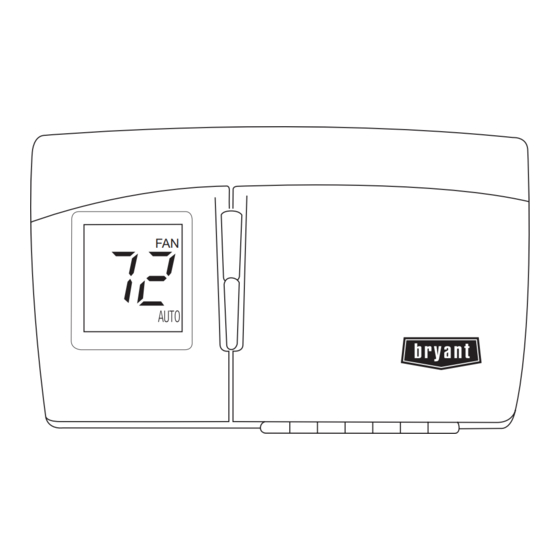
FAN
TSTATBBNAC01-C
TSTATBBNHP01-C
TSTATBBN2S01-C
HEIGHT (IN.)
WIDTH (IN.)
3-1/2
Fig. 1—Bryant Non-Programmable Thermostat
• Close to or in a frequently used room, preferably on an inside
partitioning wall.
• On a section of wall without pipes or duct work.
Thermostat should NOT be mounted:
• Close to a window, on an outside wall, or next to a door leading
to the outside.
• Exposed to direct light and heat from a lamp, sun, fireplace, or
other temperature-radiating object which may cause a false
reading.
• Close to or in direct airflow from supply registers and return-air
grilles.
• In areas with poor air circulation, such as behind a door or in
an alcove.
II. SELECT MODEL
AC Model (1-stage cool, 1-stage heat) is to be used for single-
stage heating and/or cooling applications only. It CANNOT be
used with optional outdoor temperature sensor. (See Table 1.)
HP Model (1-stage cool, 2-stage heat) can be used with a
single-speed heat pump (HP), or an air conditioner (AC) with a
2-stage furnace or fan coil. Software Option 5 selects HP/AC
operation. This thermostat comes configured from the factory as a
heat pump thermostat. Select AC in software Option 5 for AC
operation. When AC operation is selected, the O/W2 terminal is
converted from a reversing valve output (O) to a second-stage heat
output (W2). This output can be used to control 2-stage furnaces or
2-stage electric heat in fan coils. (See Table 1.)
2S Model is for 2-speed compressor systems only (HP and AC).
Output Y1 controls compressor low speed and output Y/Y2
controls compressor high speed. (See Table 1.)
II TSTAT-0-34
08-04
A04101
DEPTH (IN.)
5-3/4
1-3/8
Advertisement

Related Manuals for Bryant TSTATBBN2S01-C


Summary of Contents for Bryant TSTATBBN2S01-C
- Page 1 INTRODUCTION Bryant thermostats are wall-mounted, low-voltage thermostats which maintain room temperature by controlling the operation of a heating and air conditioning system. Separate heating and cooling setpoints, plus auto changeover provide maximum comfort and flexibility.
-
Page 2: Install Thermostat
NOTE: If the FAN button is pressed again or if no button is pressed for 3 min, the thermostat will exit the configuration mode and return to normal operation. To reenter the configuration mode, the FAN button must be pressed and held for 15 seconds again. - Page 3 FAN button to exit configuration mode. E. Option 05 — HP and 2S / AC Configuration This configuration is available on HP and 2S models only. Selecting AC allows the installer to use an HP or 2S thermostat in an AC application. TO SELECT: 1.
- Page 4 R and C. It is not available when the thermostat operates from batteries. In OF (off) mode, this function is disabled. The thermostat backlight will normally be off. It turns on with any button press and stays on for 10 seconds in between button presses.
-
Page 5: Check Thermostat Operation
6. Use up and down buttons to select another Option, or press FAN button to exit configuration mode. M. Option 19 — Equipment Present This selection informs the thermostat of the heat, cool, and fan capabilities of the installed equipment. Select number 2, 3, or 4. Default is 4. - Page 6 AC01-C HP01-C HP01-C 2S01-C 2-Speed AC 2S01-C 2-Speed HP Model Numbers: TSTATBBNAC01-C, TSTATBBNHP01-C, TSTATBBN2S01-C Note: AC = Air Conditioner, HP = Heat Pump, 2S = 2-Speed, N/A = Not Applicable SINGLE-STAGE MODEL AC 01-C THERMOSTAT FURNACE 24 VAC HOT 24 VAC COMM...
- Page 7 MODEL HP 01-C TYPICAL THERMOSTAT FAN COIL 24 VAC HOT 24 VAC COMM HEAT STAGE 1 W/W1 COOL STAGE 1 Y/Y2 HEAT STAGE 2 O/W2/B OUTDOOR See notes 2, 4, 6, 10 and 11 SENSOR CONNECTION Fig. 6—Single-Speed Air Conditioner...
- Page 8 MODEL 2S 01-c TYPICAL THERMOSTAT FAN COIL 24 VAC HOT 24 VAC COMM HEAT STAGE 1 W/W1 COOL STAGE 2 Y/Y2 HEAT STAGE 2 O/W2/B COOL STAGE 1 OUTDOOR SENSOR CONNECTION See notes 2, 4, 5, 6, 8, 10 and 11 Fig.
- Page 9 MODEL 2S EASY SELECT THERMOSTAT AIR CONDITIONER TERMINAL BOARD J1 JUMPER 24 VOLT HOT 24 VOLT COMM COOL STAGE 2 Y/Y2 Y/Y2 HEAT STAGE 1 W/W1 REMOVE J2 JUMPER FOR HEAT STAGING HEAT STAGE 2 O/B/W2 COOL STAGE 1 OUTDOOR...
-
Page 10: Wiring Diagram Notes
7. O/W2/B energizes reversing valve in cooling or heating. See Option 10. 8. Refer to outdoor equipment Installation Instructions for proper setup. 9. If system is wired per diagram, the ACRDJ (jumper) on furnace control board should be removed to allow thermostat to control outdoor unit staging. - Page 11 ERROR CODES -- — If the thermostat cannot properly read room temperature, the display will indicate -- (2 dashes) and all outputs (except the fan if on) will turn off. This is to prevent operation of the equipment if the thermostat has failed.
- Page 12 Backlight Configuration: (On = Continuous; Off = Backlight with Keypress; Default = Off) Equipment Present (2, 3, 4); Default = 4 Keypad lockout (Off or On: Default = Off) © 2004 Bryant Heating & Cooling Systems 7310 W. Morris St. Indianapolis, IN 46231 Thermostat Model No. —12—...
Need help?
Do you have a question about the TSTATBBN2S01-C and is the answer not in the manual?
Questions and answers