
Related Manuals for Power Science CF-3K-12 Series


Summary of Contents for Power Science CF-3K-12 Series
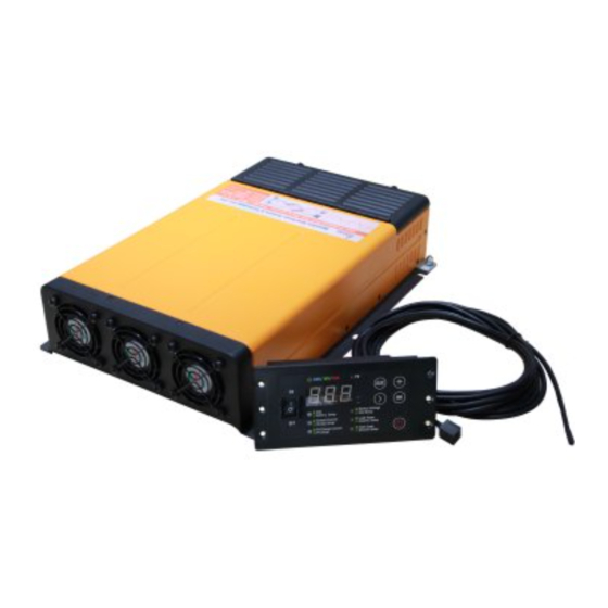
- Page 1 Series CF(M)-3K-12 Inverter+Charger+MPPT SuperCombi User Manual PowerPlus Australia Group Pty Ltd.
-
Page 2: Safety Precautions
Safety Precautions Please read the Safety Precautions before installing or using the SuperCombi CF(M)-13K-12 series products. Be sure to observe all precautions without fail. Failure to observe these instructions properly may result in personal damage, or personal injury which depending on the circumstances may be serious and cause loss of life. - Page 3 WARNINGS 1. Do not expose the machine to the environment such as rain, moisture, mist, dust, high temperature and so on or place it in the bilge. 2. Keep away from the fire and welding processes. 3. Use good quality wire with appropriate length and wire diameter. The SuperCombi may be damaged and its performance would be reduced if the wire does not meet the requirement.
-
Page 4: Table Of Contents
Contents Safety Precautions...................... 2 1. Product Introduction....................6 1.1 Basic Information..................6 1.2 Model Definition.................... 7 1.3 Application Areas..................9 2. Structure and Dimensions................... 10 2.1 Dimension and Mounting Holes Chart............ 10 2.2 Device Interface..................11 2.3 Wiring Cabin....................11 2.4 Display/Settings Panel................12 3. - Page 5 5.6 Turn Off the Panel Manually..............23 5.7 Emergency Mode..................24 6. Special Functions....................24 6.1 Dual AC outputs..................24 6.2 Charge Pro Function.................. 25 6.3 Load Priority....................26 6.4 On-Grid Supply................... 26 6.5 Separate Supply..................27 6.6 Wire Compensation..................27 6.7 Battery Capacity Testing................28 6.8 Start Battery Charging................
-
Page 6: Product Introduction
“The series CF(M)-3K-12 Charging-Inverter-MPPT All-in-One machine” (hereinafter referred to as “SuperCombi”) is independently developed by Power Science Technology Co., LTD.. This power electronic transformation device featured with high power density and super large charging current is integrated with charger, inverter and photo-voltaic MPPT controller functions. It is achieved by the patented bidirectional convert technology: ... -
Page 7: Model Definition
CF(M)-3K-12 SUPERCOMBI USER’S GUIDE 1.2 Model Definition The model format is shown below: Example: In which: Spec. Values Solar Panel MPPT M: With MPPT module Module Empty: Without MPPT module Invert Power 2K: 2000W; 3K: 3000W 200: 200A/150: 150A/100: 100A Max. - Page 8 CF(M)-3K-12 SUPERCOMBI USER’S GUIDE G: With On-Grid Supply Function. Find more in 6.4 On-Grid Supply. Invert Enhanced S: With Power Support Function. Find more ④ Function in 6.5 Separate Supply. Empty: Without Invert Enhanced Function P: The SuperCombis can work in Parallel ⑤...
-
Page 9: Application Areas
CF(M)-3K-12 SUPERCOMBI USER’S GUIDE 1.3 Application Areas Electric Tools: round saws, electric drills, grinder, buffers, weeding machine, air compressors. Office equipment: computer, printer, display, fax machine, scanner Household products: Fixed frequency, inverter air conditioner, hair dryer, vacuum cleaner, fan, fluorescent lamp, incandescent lamp, electric razor, electric sewing machine. -
Page 10: Structure And Dimensions
CF(M)-3K-12 SUPERCOMBI USER’S GUIDE 2. Structure and Dimensions 2.1 Dimension and Mounting Holes Chart The maximum size of the SuperCombi is 391*271*82mm. The specific dimensions charts are shown as in Figure 1. Fig 1. Dimension and Mounting Holes... -
Page 11: Device Interface
CF(M)-3K-12 SUPERCOMBI USER’S GUIDE 2.2 Device Interface The installation surface is shown below as Fig 2. Fig 2. The Installation Surface of the SuperCombi Each part is defined as shown in table 1: Function definition PV Input ① AC IN/OUT ②... -
Page 12: Display/Settings Panel
CF(M)-3K-12 SUPERCOMBI USER’S GUIDE Fig 3. The Wiring Cabin 2.4 Display/Settings Panel Display / settings panel are shown in Fig 4 and 5: Fig 4. Display Panel Diagram (Front) - Page 13 CF(M)-3K-12 SUPERCOMBI USER’S GUIDE Fig 5. Display Panel Diagram (Back) In which: (10) Dial Switch for Auto Invert/Floating (1) Menu Charge (2) Parameter Unit (11) PageDown/ Buzzer sound off (3) PV Indicator (12) On/Off (4) Working Indicator (13) Buzzer (5) Parameter Value (14) Remote (6) Rocker Switch (On/Off/Energy (15) Reserved...
-
Page 14: Installation Instruction
CF(M)-3K-12 SUPERCOMBI USER’S GUIDE 3. Installation Instruction Note: Before installing, make sure that the Emergency Manual Switch (Figure 6) of the SuperCombi is OFF. Otherwise, you will face the risk of battery damage! Except the "emergency ", this switch must be kept OFF at other times. -
Page 15: System Wiring Diagram
CF(M)-3K-12 SUPERCOMBI USER’S GUIDE Fig 7. Super-Combi Installation Space Diagram 3.2 System Wiring Diagram Fig 8. System Connection Diagram... -
Page 16: Cabling
CF(M)-3K-12 SUPERCOMBI USER’S GUIDE 3.3 Cabling Cabling Position Recommend Cable Specification Copper Cable with the cross sectional AC IN area larger than 6mm Copper Cable with the cross sectional AC OUT1: Power area larger than 6mm OUT2: Short Copper Cable with the cross sectional Break area larger than 6mm Copper Cable with the cross sectional... -
Page 17: Match The Battery And Current
CF(M)-3K-12 SUPERCOMBI USER’S GUIDE 3.4 Match the Battery and Current For charging safety, the "maximum charging current" of the SuperCombi should match the charge current recommended by the battery factory to avoid the risk of damage to the battery due to the mismatch of charging current. Note that any accidental loss or damage caused by the mismatch of charging current, battery damage, is not within our responsibility! 4. -
Page 18: Charge Current
CF(M)-3K-12 SUPERCOMBI USER’S GUIDE Dead Floating Battery Type Battery Max LBCO Voltage Voltage Voltage 14.1V 13.7V 10.2V AGM 1 13.8V 13.4V 10.2V AGM 2 14.3V 13.7V 10.2V Flooded 14.8V 13.3V 10.2V Lithium Iron 14.5V 13.5V Lithium 7.2V 12.6V 11.7V Ternary Table 4. -
Page 19: Grid Limit
CF(M)-3K-12 SUPERCOMBI USER’S GUIDE 12.5%, the calculation result is: 100 * 12.5% = 12.5A Note: (i) If the user has plenty of time, it is recommended to reduce the "charging current" to increase the battery life. (ii) If you charge the battery in a limited time, you can increase the "charging current"... -
Page 20: Auto Invert
CF(M)-3K-12 SUPERCOMBI USER’S GUIDE Fig 12. Grid Limit Selector 4.4 Auto Invert Users can enable or disable Auto Invert function by different setting of the dip switch on the rear of the remote panel. (See Figure 13). 1. When the Auto Invert function is enabled, the SuperCombi will output AC power automatically when the SuperCombi is disconnected from the Grid;... -
Page 21: Float Charge
CF(M)-3K-12 SUPERCOMBI USER’S GUIDE 4.5 Float Charge The user can enable or disable the Floating Charge function by varying setting of the dial switch (See Fig 13). 1. When the Floating Charge function is enabled, the SuperCombi will still charge the battery at very small current to compensate the self-discharging current;... -
Page 22: Ac Charge
CF(M)-3K-12 SUPERCOMBI USER’S GUIDE status to reduce the loss. After 5 minutes, the SuperCombi will enter into Sleep status to further reduce the loss. Fig 14. Energy Save Mode 5.3 AC Charge When connected to the Grid, the SuperCombi will work as a charger unless the Rocker Switch is in the center off position. -
Page 23: Auto Sleep
CF(M)-3K-12 SUPERCOMBI USER’S GUIDE power off. Under PV charging mode, the PV indicator will turn flashing green (see Appendices). There are 3 working statuses as follow: Under inverting condition: The solar and the battery will provide DC power together for AC inverting, but the solar power will have the priority to provide up to 500W energy for inverting. -
Page 24: Emergency Mode
CF(M)-3K-12 SUPERCOMBI USER’S GUIDE Fig 15. Turn On/Off the Panel Manually 5.7 Emergency Mode After setting up the control parameter for the first time, if the rocker switch on the panel cannot turn on/off the machine. Users can turn on/off the machine by the manual switch. -
Page 25: Charge Pro Function
CF(M)-3K-12 SUPERCOMBI USER’S GUIDE Fig 16. Dual AC Output Internal Structure AC output 1(Power): The ‘Power’ output is directly connected with AC IN. When SuperCombi is connected with the grid, the port of Power can supply AC power directly from grid; When SuperCombi is disconnected with the grid, the port of Power cannot output AC. -
Page 26: Load Priority
CF(M)-3K-12 SUPERCOMBI USER’S GUIDE 6.3 Load Priority If the power supply of gird is insufficient, the Load Priority function will make sure the load has the priority to get the power and only the remainder of the power will be charged to the battery. Note: If the total load is higher than the limit of AC IN, the gird breaker may trip, unless you choose On-Grid Supply function. -
Page 27: Separate Supply
CF(M)-3K-12 SUPERCOMBI USER’S GUIDE Fig 19. On-Grid Supply Function Example 6.5 Separate Supply With the separate power supply function being selected, when the SuperCombi is used in areas where grid connection is not allowed, the mains can only supply power to the ‘Power’ end, if the total load current is greater than the set ‘Maximum Mains Current’. -
Page 28: Battery Capacity Testing
CF(M)-3K-12 SUPERCOMBI USER’S GUIDE voltage of the DC port of the SuperCombi is higher than the actual voltage of the battery poles during charging, which results in a longer charging time; Otherwise, the voltage of the DC-side port of the SuperCombi is lower than the actual battery poles voltage during inverting, causing the battery to stop discharging before it reaches the discharge cutoff voltage. -
Page 29: Extended Functions
CF(M)-3K-12 SUPERCOMBI USER’S GUIDE 7. Extended Functions The functions described in this section can work only with our control panels. 7.1 Charger/Inverter Parameter Customization Besides the built-in 6 battery types, the SuperCombi also supports the advanced users to customize battery charging parameters. It means that the SuperCombi can be fit for almost any kind of batteries. - Page 30 CF(M)-3K-12 SUPERCOMBI USER’S GUIDE function, the SuperCombi can charge the "Dead Battery" according to a unique charging software algorithm. Warning: Please make sure the low voltage dead battery is undamaged and rechargeable. Any accidental loss conducted by misusing this function is not within the scope of our responsibility! Please closely monitor the battery closely during charging.
-
Page 31: Specifications
CF(M)-3K-12 SUPERCOMBI USER’S GUIDE 8. Specifications Parameter Index Inverter Mode Nominal Voltage 12VDC Input Voltage Range 9~15VDC Input Current (Max.) 350A DC Input Stand-By Current 0.4A Input Over Voltage Protection ≥15.5VDC Input Under Voltage Protection ≤8.9VDC CF(M)-3K-12-A: 220VAC ±3% Output Voltage CF(M)-3K-12-B: 230VAC ±3% CF(M)-3K-12-C: 240VAC ±3% Continuous Output Power... - Page 32 CF(M)-3K-12 SUPERCOMBI USER’S GUIDE Side Battery Temp. Protection Battery Temperature Sensor (Optional) AC Output Protection Short Circuit / Overload AC Side AC Input Protection Over Voltage / Under Voltage Others Temperature Protection, Fan Error, Internal Error Protection Environment Full Load -20℃~50℃...
-
Page 33: Troubleshooting
CF(M)-3K-12 SUPERCOMBI USER’S GUIDE 9. Troubleshooting Code Fault Type Possibility Solution 1. Start the Charge mode 2. To check whether the The battery is over SOC Low cable of battery side is discharged reasonable 3. Fasten the battery wiring 1. Disconnect or poor 1. - Page 34 CF(M)-3K-12 SUPERCOMBI USER’S GUIDE Inverter The load exceeds range Reduce the load of inverter overload in specification 1. Check the loading and try Too large loading stroke Short circuit of to replace it. current or short circuit of inverter 2. Check if there is a short inverter circuit on the inverter side.
- Page 35 CF(M)-3K-12 SUPERCOMBI USER’S GUIDE temperature too high over temperature scheme Contact the distributors to MPPT internal MPPT internal error return to the factory for malfunction inspection...
-
Page 36: Appendices
CF(M)-3K-12 SUPERCOMBI USER’S GUIDE 10. Appendices Indicator Color Status Description Solid AC invert is working . Solid AC charge is working. The on/off button was pressed. Charging Working Flash stopped and AC output is on, AC power Indicator comes from the grid. Solid Stand by mode. -
Page 37: Warranty
CF(M)-3K-12 SUPERCOMBI USER’S GUIDE 11. Warranty PowerPlus provide 2-year warranty for this product from the date purchased. PowerPlus Australia Group Pty Ltd. will take full responsibility to the product. Please be care that if the product is damaged because of improper installation, immersion, foreign matter invasion or any malfunction caused by users, PowerPlus Australia Group Pty Ltd. - Page 38 Power Science Technology Co., Ltd. Headquarter Australia Branch Add: The 2nd Floor, Building 1, Add: 5/17-25 Kinder St., Hengchangrong Baoan, Campbellfield, VIC 3131 Shenzhen P.R. China 518108 Tel: +61 416 766 688 Tel: +86 755 8652 9986 Email: au@powerscience.net Email: info@powerscience.net...
Need help?
Do you have a question about the CF-3K-12 Series and is the answer not in the manual?
Questions and answers