
Related Manuals for SMA ANTENNA EXTENSION KIT

Summary of Contents for SMA ANTENNA EXTENSION KIT
- Page 1 Installation Manual ANTENNA EXTENSION KIT ENGLISH EXTANT-40-IA-en-10 | Version 1.0...
- Page 2 The information contained in these documents is property of SMA Solar Technology AG. Any publication, whether in whole or in part, requires prior written approval by SMA Solar Technology AG. Internal reproduction used solely for the purpose of product evaluation or other proper use is allowed and does not require prior approval.
-
Page 3: Table Of Contents
Table of Contents SMA Solar Technology AG Table of Contents Information on this Document..................... Validity ................................Target Group ..............................Symbols................................Typographies ..............................Nomenclature ..............................Safety ............................Intended Use..............................Safety Information ............................Scope of Delivery ......................... Mounting............................Mounting position............................Mounting the Antenna ............................ 10 Troubleshooting.......................... -
Page 4: Information On This Document
SMA Solar Technology AG 1 Information on this Document Validity This document is valid for the Antenna Extension Kit (Product "EXTANT-40"). You can find the latest version of this document at www.SMA-Solar.com. Target Group The tasks described in this document must only be performed by qualified persons. Qualified persons must have the following skills: •... -
Page 5: Nomenclature
1 Information on this Document SMA Solar Technology AG Typography Example • Connects several elements to be > • Select Settings > Date. selected • Button or key to be selected or pressed [Button] • Select [Next]. [Key] Nomenclature Complete designation... -
Page 6: Safety
• STP 50-40 (Sunny Tripower CORE1) The inverter still complies with the standard after the product has been installed. The product must only be used in countries for which it is approved or released by SMA Solar Technology AG and the grid operator. - Page 7 2 Safety SMA Solar Technology AG Increased electromagnetic radiation through the antenna During operation, the antenna produces an electromagnetic field and can interfere with other devices (e.g., pacemakers) due to electromagnetic interference. • Persons must not remain closer than 20 cm to the antenna for long periods of time.
-
Page 8: Scope Of Delivery
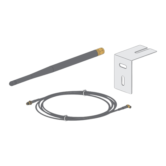
3 Scope of Delivery SMA Solar Technology AG 3 Scope of Delivery Check the scope of delivery for completeness and any externally visible damage. Contact your distributor if the scope of delivery is incomplete or damaged. Figure 1: Components included in the scope of delivery... -
Page 9: Mounting
4 Mounting SMA Solar Technology AG 4 Mounting Mounting position A N T P 2 0 V F - K I D : S - K P 2 F C C 4 4 0 A I C : 9 . 3 0 V... -
Page 10: Mounting The Antenna
4 Mounting SMA Solar Technology AG The mounting location of the antenna is crucial for the quality of the wireless connection. Radio waves are emitted in circles from the longitudinal side of the antenna. A circular dead spot begins at the tip of the antenna. If you place the receiver in this dead spot, the receiver cannot receive any radio waves from the antenna. - Page 11 4 Mounting SMA Solar Technology AG 2. If necessary, attach the cable gland to the inverter: • Push the sealing plug from the inside out of the enclosure opening and retain it for later decommissioning. • Unscrew the counter nut from the supplied cable gland.
- Page 12 4 Mounting SMA Solar Technology AG • Route the antenna cable with the cable end with the plug through the swivel nut and the desired hole of the two- hole cable support sleeve. • Push the two-cable support sleeve along with the antenna cable back into the cable gland. Ensure that any unused openings of the two-hole cable support sleeve are sealed with sealing plugs.
- Page 13 4 Mounting SMA Solar Technology AG • Tighten the counter nut. • Hand-tighten the antenna on the antenna extension cable plug. Danger to life due to electric shock from touching an ungrounded product Touching an ungrounded product can cause a lethal electric shock.
-
Page 14: Troubleshooting
5 Troubleshooting SMA Solar Technology AG 5 Troubleshooting Problem Cause and corrective measures The radio range has not im- The problem can be caused by one of the following: proved despite the antenna. • The inverter has not recognized the antenna automatically. -
Page 15: Decommissioning
6 Decommissioning SMA Solar Technology AG 6 Decommissioning Removing the Antenna Required tools: ☐ Long-nosed pliers Procedure: Danger to life due to high voltages of the PV array When exposed to sunlight, the PV array generates dangerous DC voltage, which is present in the DC conductors and the live components of the inverter. -
Page 16: Contact
7 Contact SMA Solar Technology AG 7 Contact If you have technical problems with our products, please contact the SMA Service Line. We require the following information in order to provide you with the necessary assistance: • Inverters: – Serial number – Firmware version –... - Page 17 7 Contact SMA Solar Technology AG United Arab SMA Middle East LLC India SMA Solar India Pvt. Ltd. Emirates Abu Dhabi Mumbai +971 2234 6177 +91 22 61713888 SMA Online Service Center: www.SMA-Service.com SMA Solar (Thailand) Co., Ltd. 대한민국 SMA Technology Korea Co., Ltd.
- Page 18 www.SMA-Solar.com...
Need help?
Do you have a question about the ANTENNA EXTENSION KIT and is the answer not in the manual?
Questions and answers