Table of Contents
Advertisement
Quick Links
Advertisement
Table of Contents

Subscribe to Our Youtube Channel
Related Manuals for Foxtech T30


Summary of Contents for Foxtech T30
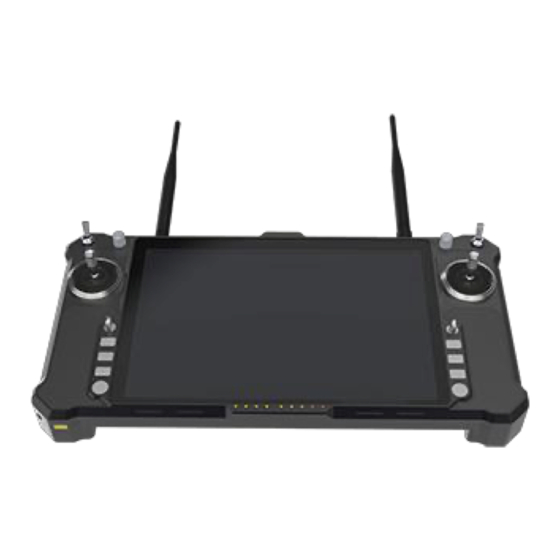
- Page 1 User Manual Oct, 2019 T30 Handheld Ground Control Station...
-
Page 2: Table Of Contents
Content 目录 User Manual..................... 3 1. Disclaimer.....................3 2. Product Precautions..................3 2.1 Installation Note................4 2.2 Precautions for Use................4 3. Product Introduction..................5 4. Item List......................5 5. Product Instruction..................8 5.1 Receiver V20..................8 5.3 Remote Control Instruction............11 5.2 Receiver V30..................10 5.4 V20 Receiver Installation and Connection........12 5.5 V30 Receiver Installation and Connection........ -
Page 3: User Manual
2. Product Precautions 1) T30 ground terminal is matched with airborne end to use together. 2) The ground terminal is with built-in 12v battery (3S lithium battery). -
Page 4: Installation Note
3. Please check the surrounding environment to ensure that there is no interference from other devices, otherwise T30 data transmission performance will be seriously affected. 4. Ensure that the antennas are free from obstacles and... -
Page 5: Product Introduction
please charge the remote control timely. If the remote control is turned off, the receiver has entered the state of out-of-control protection. Stop using it when the battery is too low. Don't rely on the device's low-power alarm, which is only a precaution and tells you when to charge. It takes about 5-6hs to be fully charged. -
Page 6: Item List
4. Item List Option 1 T30 remote controller×1 V20 receiver x 1 Accessories Power Charger*1 Receiver upgrade Lan-to-4 pins supply configuration line*1 cable*1 line*1 Used for firmware Power for Charge for For module upgrading receiver remote Parameter and parameters (DC:7.4-12V, Li... - Page 7 Option 2 T30 remote controller×1 V30 receiver x 1 Accessories Power supply Charger*1 3-pin wire*3 HDMI cable*1 connection wire*1 Data Power for Charge Used for transmission receiver connecting port, used for remote camera or (DC:7.4-12V, inserting SBus control camera gimbal...
-
Page 8: Product Instruction
5. Product Instruction 5.1 Receiver V20 Front view ①Video transmission CPU indicator: light will be continuously ON in normal working condition. ②Data receiving indicator: light will flicker in the condition of data receiving. - Page 9 ③Date transmitting indicator: light will flicker in the condition of data transmitting. ④Signal strength indicator: S3 ON, signal is weak; S3 and S2 ON, signal is moderate; S3, S2 and S1 ON, signal is strong. ⑤Key switch: used for firmware upgrading, out-of-control protection settings, restore the default transmission settings.
- Page 10 By default, the S-BUS1 and S-BUS2 interfaces output the CH1 to CH16 of the remote control to 1-16 channels. 5.2 Receiver V30 Front view ①Video transmission CPU indicator: light will be continuously ON in normal working condition. ②Data link indicator: indicator will be continuously ON when the connection of TX and RX is successfully established.
- Page 11 Side view ①Data transmission port: TTL, transparent transmission ②SBus 1 port: used for connecting flight controller or payload ③SBus 2 port: used for connecting flight controller or payload ④Power supply port: 7.4-12V ⑤HDMI video input interface: connecting camera ⑥USB port: used for firmware upgrading and parameters setting ⑦AV video input interface: used for analog video input.
-
Page 12: Remote Control Instruction
5.3 Remote Control Instruction ①Left and right rockers: corresponding T1, T2, T3 and T4, used for flight control ②Four three-stage switches: corresponding SA, SB, SD, SE ③Left and right rotary knobs: corresponding LD and RD ④Two buttons(or three-stage switches:corresponding S1, S2 (or SC, ⑤Left and right deflector rods: corresponding T5 and T6(can be dialed to the middle) ⑥9 key channels: corresponding F1~F9... -
Page 13: V20 Receiver Installation And Connection
⑮Charging interface: connecting 12.6V DC adapter ⑯Battery connection interface: used for connecting battery 5.4 V20 Receiver Installation and Connection 1. Connecting antennas to SMA port of Rx. 2. Fix the receiver to the appropriate position of the aircraft by using double-sided tape. -
Page 14: V30 Receiver Installation And Connection
6. Remote Controller Operation 6.1 Power on and Power off of Remote Controller and the Computer In the process of turning on/off the device T30,please pay attention to the power button, power indicator and 4 power indicators (25%,50%,75%,100%) and 5 data link indicators... - Page 15 1. Long press the power button, the power indicator light is on, and then according to the speed of the release action of the button to decide whether the computer is turned on or not. 2. Release the power button after the first short sound of the buzzer.
- Page 16 data receiving V30: Off RS1,RS2,RS3 ON Strong signal RS1, RS2 ON,RS3 OFF Moderate signal Signal strength RS1 ON,RS2, RS3 OFF Weak signal indicator RS1, RS2, RS3 RS1,RS2,RS3 OFF or Show the running No connection horse lights Firmware upgrading status flicker in configuration mode Flicker, with a continuous short...
- Page 17 Indicator light shows normal, buzzer with Remote controller idle continuous short sound alarm 6.3 V20 Receiver Indicator Instruction Indicator Status Define SBUS1, SBUS2 no signal transmission L1 indicator SBUS1, SBUS2 signal Fast flashing transmission The receiver is in high frequency configuration L2 indicator Continuously ON mode with no power...
- Page 18 6.4 Operation Instruction of V20 in Normal Connection Status Start the remote controller, V20 receiver is powered on. After the successful connection of 2 modules, CPU indication will be ON, signal indicators are constant, this process takes about 1 min, the device can work normally.
- Page 19 1. Power on the remote control and tablet and open the Tablet Tool Platform. Go to the main interface as shown above. 2. Double-click the <Parameters Setting Software> icon to enter the software. 3. <Firmware Upgrade> can upgrade firmware for remote control and receiver.
- Page 20 After the calibration is completed, toggle each joystick to see if the parameters setting software display matches the action to verify that the calibration was successful. When the RD and LD knob switches hit the middle position, they will give a“didi”sound.
- Page 21 steering stroke can be adjusted from -150 to 150. The default is - 100 to 100. Do not adjust if there is no special need. 3. Out of control protection settings: click on the small white box, when there is a <√> in the white small box, the out of control protection function of the current channel works;...
- Page 22 Save configuration: save the current configuration as a configuration file for easy finding Restore default: restore all parameters of the current page to default values After each configuration change, click <write data button> and the changed configuration can take effect. When the remote control mode is configured as American mode, Japanese mode and Chinese mode, the control mode is shown below.
- Page 23 Right joystick Rise Fall DOWN Left Right Turn left Turn right The default control mode of T30 is the American mode. This manual uses the American hand as an example to illustrate how the remote control is operated. 6.9 Throttle Hold...
- Page 24 4. Hardware voltage is the real-time voltage of remote control battery. 5. Restore Factory Setting. T30 is with powerful function, so there are many parameters that can be set. We can restore the factory settings of T30 with one key.
- Page 25 ②If the operation is wrong, click cancel button. If you do want to restore all parameters to factory Settings, click ok. ③ After restoring factory settings, all parameters (including analog channel calibration, SBUS setting, channel holding, throttle holding, idle alarm time, low voltage alarm voltage, etc.) will be restored to factory default values.
- Page 26 adjusting software). At this time, stir any joystick or dial lever and the alarm sound will be automatically turned off. When the "alarm time" is set to 0 minutes, the alarm function will be cancelled. Low power alarm The battery voltage is lower than the set alarm voltage (default:10.6 V) , the remote control will issue "didi"...
- Page 27 3. Change serial port baud rate. (Please modify baud rates of both airborne end and ground end simultaneously) Power on the module and CPU light will be ON. Connect the computer and the LAN port of V20 receiver with LAN-to-4pin line. (The LAN port of the internal module of the remote control has been connected to the network port) The computer must set its network settings (TCP/IP...
- Page 28 Open the browser and put the IP address (airborne end: 192.168.168.11; Ground end: 192.168.12) to the...
- Page 29 address bar. Then enter user name and password. User name:admin; Password:ADMIN; Please change the baud rate according to your needs. Click submit when the change is complete. Please mark the changes as shown in the figure below. Do not modify other values. Otherwise, the module may not work properly.
- Page 30 7.2 LAN port The LAN port of the internal module of the remote control has been connected to the network port and can be directly used. The receiver V20 can connect the computer with the LAN port of the V20 receiver by the LAN-to-4pin line. Local video can be transmitted using LAN port.
- Page 31 Modify the IP address based on your requirement. Click submit after the modification is completed. Do not modify the data of other columns randomly. Note! For the ground end of the video transmission system, in Default Gateway column, fill in LAN port IP of airborne end.
- Page 32 7.3 Fast Reset and Configuration of Video Transmission Module If your video transmission device becomes unresponsive during use, you need to restore to factory settings. The airborne end needs to be configured to master mode and the ground end needs to be configured in slave mode. (Note: the current version of the ground end does not support reset, and the subsequent version will be added) 7.3.1 Fast Reset of Video Transmission Module...
- Page 33 6.8 Channel Hold 6. Select channel hold control switch 7. Select the gear position where the control switch trigger remains."0" represents low gear, "1" represents middle gear and "2" represents high gear. Three gears can be used separately. Choose the channel hold. 9.
- Page 34 7.3.2 Fast Configuration of Video Transmission Receiver Module Power on the module and CPU light will be ON. Connect PC and LAN port of airborne end by LAN cable. The computer must set its network Settings (TCP/IP properties) to automatically obtain the IP address (refer to baud rate modification of serial port ).
- Page 35 ⑥Pls filll in IP ADDRESS: 192.168.168.11; IP Subnet Mask: 255.255.255.0; and click submit, the parameters can be written. Then you need to log in again by the newly written IP address to continue the following configuration. Or you can also fill in the appropriate IP address according to your own needs.
- Page 36 Note!Channel Bandwidth,Channel Frequency, Network ID of the airborne end and ground terminal need to be configured the same. In this way, the communication can be established. ⑧ Click Serial->Settings, choose Date , after parameters configuration, click submit. The baud rate of this port must be 115200.
- Page 37 ⑨Choose Serial->USB0, this port is used to configure serial port parameters. Baud rate can be adjusted according to the own requirement. Click submit when the write is complete. ⑩Choose Admin->Logout, click Logout Now.
- Page 38 7.3.3 Fast Configuration of Video Transmission Module of Remote Controller Enter the parameter configuration interface (refer to airborne end, the only difference is that the input IP address is 192.168.168.2). After log in, pls choose Network->LAN->Edit。 Configure the parameters as shown in the figure below, and click submit after the configuration is completed.
- Page 39 After log in,choose wireless->RF, Pls do the configuration as below: After finishing the written, click submit. (Frequency and transmission power can be selected based on your requirement) Note! Channel Bandwidth, Channel Frequency, Network ID of the airborne end and ground terminal need to be configured the same.
- Page 40 ⑤Click Serial->Settings, choose Data. After parameters configuration, click submit. The baud rate of port must be set 115200. It cannot be modified, otherwise the communication will be affected. ⑥ Choose Serial->USB0, this port is used for parameters configuration of serial port. The baud rate can be adjusted...
- Page 41 based on the own requirement. Click submit when the write is completed. Note that the serial port parameters of Remote Server port should be consistent with theat of the airborne end (USB0) Local Listening port. ⑦Choose Admin->Logout, click Logout Now. Note: 1.
-
Page 42: V30 Parameters Configuration
Note: The T30 is matched with COM6 and the V30 is matched with the port number of the tool. You must not send a newline return. - Page 43 4. Enter configuration command Enter the corresponding configuration command and wait for the device to return OK, indicating that the command was sent successfully. The device returns <OK> to indicate successful modification. If showing <ERROR> , it indicates the command input is wrong or the parameter is invalid.
- Page 44 Supporting instruction list Type Command Parameter Parameter value instruction Low power Setting RF Moderate power transmitting AT^SPWR=_ power High power 9600 Baud rate 9600 14400 Baud rate 14400 19200 Baud rate 19200 Setting baud 38400 Baud rate 38400 rate of serial AT^SBR=_ 56000 Baud rate 56000...
-
Page 45: V30 Video Output (Vlc)
Type Command Parameter Parameter value instruction Lower power Query RF transmitting AT^GPWR Moderate power power High power 800MHz 800MHz Query AT^GCHN 1.4GHz 1.4GHz frequency 2.4GHz 2.4GHz Query baud xxxxxx Current baud rate rate of serial AT^GBR value port Query KEY AT^GKEY XXXXX Current KEY... - Page 46 ON, which indicating the successful connection of airborne end and ground terminal. The TCP/IPv4 attribute is configured in the T30 network connection, where the IP address is "192.168.168.xxx" (XXX is the intermediate address value from 0 to 255, 192.168.168.11 and 12,13 are reserved addresses), and the default gateway address is set to "192.168.168.1".
- Page 47 Enter the correct video streaming address URL, you can get the video image.
-
Page 48: Display Images On Mission Planer
8.3 Display images on MISSION PLANER First, verify that the video stream is available in video software such as VLC and open MISSIONPLANER; 1.Press the right mouse button (or long press) in the HUD window 2.Click VIDEO 3.Click GetGstreamer source 4.Enter the following address (Note size set and half symbols) - Page 49 5.For the first time usage, download the relevant software package and wait for the download to complete. Restart software. 6.After finishing steps 1-4, you will get the camera video source. 7.Right - click to zoom in on the ground...
-
Page 50: Display Image In Qgc
8.4 Display image in QGC First, verify the video stream is available in video software such as VLC and open MISSIONPLANER; 1. Currently, GQC does not support H.265 encoding, it is needed to input in the browser IP:192.168.168.13 to log in V30 Transmitter. - Page 51 4. Switch the flight interface and see the video transmitted by the camera or camera gimbal. 9. V20 Video Transmission Module Parameters Item Paramters Instruction 2.304-2.390GHz Frequency 2.3GHz 2.402-2.482GHz 2.500-2.570GHz Power 0.1-1w adjustable Transmission range 3-7Km Up to the environment S-Bus port 2*port Serial port...
-
Page 52: Firmware Upgrading Of V20 Receiver
adjustable Latency 10ms Power voltage 7.4-12v Bandwidth 4MHz/8MHz optional Video input interface 9.1 Firmware Upgrading of V20 Receiver 1. Click on the official website to download the firmware, select the appropriate version of the firmware and save it locally. 2. Power off the receiver and connect COM port of the receiver to the computer. - Page 53 1.Please follow the procedures strictly and make sure that all other software using ports are closed, such as serial port debugging assistant. Otherwise, the upgrade may fail. 2.Please select the corresponding firmware, if the firmware does not match, the upgrade will fail. 10.
-
Page 54: Remote Control Port
10.1 Remote Control Port The T30 computer is equipped with 6 COM ports. Among these COM ports, COM5 and COM6 are only for internal use. COM5 is the special port for the debugging software, and COM6 is the serial port for the remote controller data transmission. -
Page 55: Remote Control Antenna
10.2 Remote control antenna T30 has multiple versions of P900, V20, and no module. Depending on the version, the type and frequency of the two antennas A1 (right), A2 (left) installed on the remote control are also different. -
Page 56: Remote Control Charging
If the battery indicator shows low power, please stop the flight and charge the T30 in time. 1. Insert the output end of the adaptor into the T30 battery charging port and insert the matched adaptor into the 220V socket (adapter output: 12.6v) - Page 57 2. Enter device and printer. 3. If there is device called "chinowing hzy-joy", your remote control has HID gamepad. If not, it is not supported...
- Page 58 4.Right-click and select game controller Settings 5.Select "chinowing hzy-joy" and click on the attributes. You can see each channel in the test bar. Operate the rocker and the corresponding channel state will change accordingly. The X- axis/Y-axis, z-axis, x-rotation, y-rotation, z-rotation, dial-up and slider are analog channels.
-
Page 59: Firmware Upgrading And Operation Procedure
Note: the game controller is only supported to be used when the parameters setting software is closed. Please contact the customer service staff for other requirements. 10.5 Firmware Upgrading and Operation Procedure Please use firmware upgrade tool to upgrade the firmware of remote control and receiver respectively. - Page 60 below photo, press the power button of the remote control to start up. 3.After the PC boot is completed, open the firmware upgrade in the tool platform 4.At this time, you can see that the serial port of firmware upgrade tool has been connected, and the current hardware, firmware and other information of the remote control are displayed, as shown in the figure below: 5.Open the saved firmware file path and click the start...
- Page 61 1.Long press the power switch of the remote control, do not hear ‘didi’ sound, and the power red light only flashing once. Please confirm if the T30 is powered. 2.The receiver is powered on, but there is no signal output.
- Page 62 4.There is interference when two or more devices are started up at the same time Please check that the ID of each set must be different and the channel must be set differently to avoid interference of the same frequency. 5.The parameters setting software shows <Remote control port not found>...
- Page 63 12. T30 Specification Remote control end: Channel Control range V20:3~-7KM V30:10-15KM RF transmitting power V20: 0.1W-1W adjustable V30: 0.1-0.5W Remote control latency 40ms Battery capacity 12V/10200mAh or external battery can be connected Operating hours 3hs with full capacity Overall weight...
Need help?
Do you have a question about the T30 and is the answer not in the manual?
Questions and answers