Table of Contents
Advertisement
Advertisement
Table of Contents

Related Manuals for EMKO Proop Series


Summary of Contents for EMKO Proop Series
- Page 1 fessional perator anel User Manual...
- Page 2 PREAMBLE PROOP series HMI panels are a product with powerful features that enable you to perform your applications quickly. EMKO Proop series offers a wide selection for your projects with HMI panels starting from 4.3 '' to 10.1 '' and offering different communication and input-output options.
-
Page 3: General Features
GENERAL FEATURES • Over 100 vector-based ready elements. • Vector-based user-defined image (SVG) support. • Image support in BMP, GIF, JPG, JPEG, PNG, PBM, PGM, PPM, TIFF, XBM, XPM format. • Improved visual drawing infrastructure; antialiasing, alphablending support. • TrueType (TTF), PostScript Type1 (PFA / PFB), Bitmap Distribution Format (BDF), CID-keyed Type1, Compact Font Format (CFF), OpenType fonts, SFNT-based bitmap fonts, Portable Compiled Format (PCF), Microsoft Supports Windows Font File Format (Windows FNT), Portable Font Resource (PFR), Type 42 (limited... - Page 4 PROOP MODELS MODEL Proop.black-4.eco Proop.black-5.eco Proop.black-7.eco Proop-7L Proop-7L.wi Proop-7L.E Proop-7L.Ewi Proop-10L Proop-10L.wi Proop-10L.E Proop-10L.Ewi Proop-7C Proop-7C.wi Proop-7C.E Proop-7C.E2 Proop-7C.Ewi Proop-7C.E2wi Proop-10C Proop-10C.wi Proop-10C.E Proop-10C.Ewi Proop-10P.0.D5.D4.AC.AC Proop-10P.wi.D5.D4.AC.AC Proop-10P.E.D5.D4.AC.AC Proop-10P.Ewi.D5.D4.AC.AC Proop-10P.E2.D5.D4.AC.AC Proop-10P.E2wi.D5.D4.AC.AC...
-
Page 5: Technicial Specifications
TECHNICIAL SPECIFICATIONS Product 4,3" 5" 7" 10,1" Screen Type 4,3” TFT LCD 5” TFT LCD 7” TFT LCD 10,1” TFT LCD Display Colors 260K 260K 260K 1024x600 Resolution 480x272 800x480 800x480 Touch Method Resistive Analogue Resistive Analogue Resistive Analogue Resistive Analogue LCD Lighting Brightness (Cd / m2) 25°C 50000 Hour... -
Page 6: System Requirements
SYSTEM REQUIREMENTS Minimum system requirements for installing Proop Builder software: •1GHz or faster processor •1GB RAM •2GB of Memory (at least 500 MB of free memory) •RJ45 Ethernet network cable •USB Port Input • Windows XP, Windows Vista, Windows 7, Windows 8, Windows 8.1, Windows 10 any of the operating systems. - Page 7 ASSEMBLY 1. Prepare the section of panel where the device will be mounted in the dimensions given. 2.The sealing gaskets on the front panel of the device are installed. be sure. 3.Insert the device into the section on the panel. 4.Install mounting brackets into their slots.
- Page 8 SETUP Before starting the installation of the device,read the following warnings carefully. Before carrying out the installation of the device, it must be checked against damage that may occur during transportation. Installation and commissioning must be done by mechanical and electrical technicians. This responsibility belongs to the buyer.
- Page 9 There is no switch on the device to turn off the fuse and device energy. A switch and fuse that will turn off the energy at the supply input of the device must be added to the system by the user. It is necessary to check the supply voltage range of the device and apply the appropriate supply voltage.
-
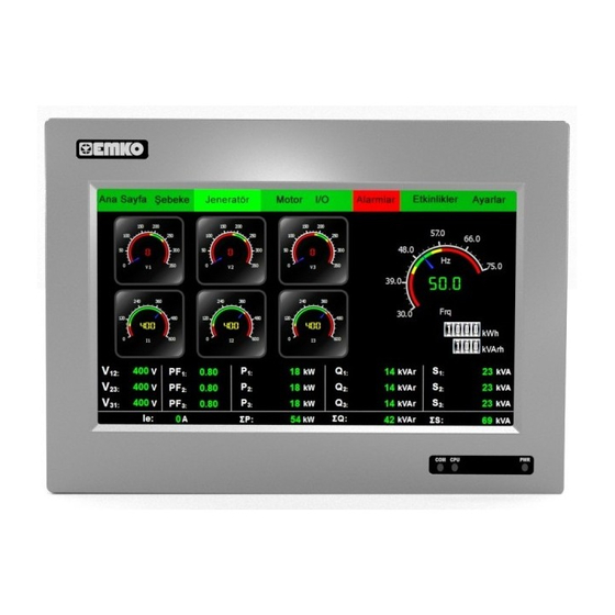
Page 10: Panel View
PANEL VIEW EMKO offers 2 different color options in Proop HMI panels, black and gray. Proop 4.3 ”and 5” economic models are only black color options and other models can choose 2 different colors. Black and Gray color views are as in Figure 1 and Figure2. - Page 11 Digital Inputs Digital Outputs RS-422 Figure2 :PROOP 7" Back view Analogue / Digital Inputs Analogue / Digital Outputs RS-422 Figure3 :PROOP 10.1" Back view...
-
Page 12: System Settings
SYSTEM SETTINGS Device system settings can only be made on the panel. In order to open the device system settings window, a button object should be added to the form page and the button type property of this button should be set as HMI settings. - Page 13 Figure6 :HMI Wi-Fi Settings Window Wi-Fi connection settings are made on the Wi-Fi tab. Ÿ The name of the network to be connected to the SSID part and the password of Ÿ the network is written in the password part. The DHCP icon is removed to get fixed IP from the network and the necessary Ÿ...
- Page 14 Figure8 :10" HMI Battery bed In 10 ”panels, the battery can be replaced by opening the cover in Figure 8. Ÿ Battery in other models The back cover must be opened for replacement. Local time zone can be defined from Locale tab. Ÿ...
- Page 15 Figure9 :HMI Lighting-Buzzer Settings Window Display brightness and buzzer on-off setting from HMI system settings Ÿ In order to open and close the buzzer during the program, assignment to $ S0 must be made. When $ S0 is 1, the buzzer will be open and 0 will be closed. $ S1 address is used to change the screen brightness.
- Page 16 The firmware and update information can be accessed from the About tab. There Ÿ is firmware version information installed on the device in the application section. PROJECT LOADING We can upload the program we made in the editor software to the HMI panel with Ÿ...
- Page 17 To install cable over PC; USB Cable 1.Connect the HMI panel from the USB device port to the PC via cable. 2. In the editor software, PROOP <-> PC Connection USB Select. 3.When the program you made from the editor software is open ına ‘To Tools / HMI Device Install '' or press F5.
- Page 18 To install programs with USB Memory: 1. Create a folder named "emko" or "proop" in the main directory in the USB memory. 2. Copy the project file (* .emkp) you prepared with the editor software into this folder. 3. Copy the image library file with the extension "* .rcc" that you used in your project to this folder where you created it.
-
Page 19: Firmware Update
FIRMWARE UPDATE Firmware updates containing specific features with HMI panel editor software is Ÿ published regularly. Current editor software, firmware updates and Information documents can be found at www.emkoelektronik.com.tr Firmware update can be done in two ways. For firmware update via PC;1.Wire the HMI panel from the USB device input to the PC with cable. -
Page 20: Factory Settings
FACTORY SETTINGS When the device is turned on, pressing the reset button shown in picture13 for 5 seconds, the device, updates and software are deleted and returned to the factory settings. Countdown and deletion of the settings can be followed on the screen. Figure13 :Reset Button INTERNAL MEMORY ADDRESS DEFINITIONS Memory Type... -
Page 21: Supported Communication Protocols
SUPPORTED COMMUNICATION PROTOCOLS Supported communication protocols are listed in the table below. SIEMENS S7-300(ISOTCP) Modbus-RTU MS/TP MODBUS BACNET SIEMENS S7-400(ISOTCP) Modbus-ASCII MODBUS BACNET SIEMENS S7-1200(ISOTCP) MODBUS Modbus TCP/IP OMRON Host Link SIEMENS S7-1500(ISOTCP) MODBUS Modbus-ASCII(Slave) OMRON FINS MODBUS Modbus-RTU(Slave) DELTA DVP Series PLC MODBUS Modbus TCP/IP(Slave) - Page 22 CONNECTIONS Device Supply Input(For PROOP 4.3,5,7 COM4 (For PROOP 7 and 10) and 10 ) COM2- COM3 (For PROOP 4.3, and 5) Terminal COM1 COM2 RS-485 RS-232 B GND Tx COM1 (For PROOP 7 ) COM2- COM3 (For PROOP 7) COM1 –...
- Page 23 Digital Inputs/Outputs (For PROOP 7) Explanation Wiring Diagram Digital Output Supply - Digital Outputs Digital Output Supply + Digital Inputs Digital Inputs NPN/PNP Selection Analogue/Digital Inputs (For PROOP 10) Explanation Wiring Diagram Analogue Input 2 Analogue Input 1 Digital Inputs Digital Inputs NPN/PNP Selection Analog/Dijital Çıkışlar (PROOP 10 için)
-
Page 24: Warranty
Cleaning the device with these solutions can reduce the mechanical reliability of the device. OTHER INFORMATIONS Manufacturer Company Information: Emko Elektronik Sanayi ve Ticaret A.Ş. Demirtaş Organize Sanayi Bölgesi Karanfil Sok. No:616369 BURSA Tel : +90 (224) 261 1900 Fax :+90 (224) 261 1912 Company Information Providing Maintenance and Repair Services: Emko Elektronik Sanayi ve Ticaret A.Ş.
Need help?
Do you have a question about the Proop Series and is the answer not in the manual?
Questions and answers