Table of Contents
Advertisement
Quick Links
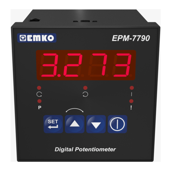
EPM-7790 72 x 72 DIN Size
Control Panel For V/F Speed Controller
- 4 Digits Display
- Easily adjustable set value from front panel
- Configurable display scale between -1999 and 9999
- Adjustable decimal point
- Set value low limit and set value high limit boundaries
- Adjustable ramp up and ramp down time
- Forward, Reverse direction outputs and error input for V/F Speed
Controller
Z
-
0/2...10V
Voltage output or 0/4...20mA
(It must be determined in order.)
- Password protection for programming and adjustment sections
Z
Current output
Instruction Manual. ENG EPM-7790 02 V00 01/07
Advertisement
Table of Contents

Related Manuals for EMKO EPM-7790


Summary of Contents for EMKO EPM-7790
- Page 1 - Forward, Reverse direction outputs and error input for V/F Speed Controller 0/2...10V Voltage output or 0/4...20mA Current output (It must be determined in order.) - Password protection for programming and adjustment sections Instruction Manual. ENG EPM-7790 02 V00 01/07...
- Page 2 ABOUT INSTRUCTION MANUAL Instruction manual of EPM-7790 unit consists of two main sections. Explanation of these sections are below. Also, there are other sections which include order information and technical specifications of the device. All titles and page numbers in instruction manual are in “...
-
Page 3: Table Of Contents
1.2 ORDERING INFORMATION 1.3 WARRANTY 1.4 MAINTENANCE 2.INSTALLATION........................... Page 2.1 GENERAL DESCRIPTION 2.2 FRONT VIEW AND DIMENSIONS OF EPM-7790 UNIT 2.3 PANEL CUT-OUT 2.4 ENVIRONMENTAL RATING 2.5 PANEL MOUNTING 2.6 INSTALLATION FIXING CLAMP 2.7 REMOVING FROM THE PANEL 3.ELECTRICAL WIRING........................ - Page 4 EU DECLARATION OF CONFORMITY Manufacturer Company Name : Emko Elektronik A.S. Manufacturer Company Address: DOSAB, Karanfil Sokak, No:6, 16369 Bursa, Turkiye The manufacturer hereby declares that the product conforms to the following standards and conditions. Product Name Control Panel For V/F Speed Controller...
-
Page 5: General Specifications
1.Preface EPM-7790 series units are designed for controlling the speed and direction of the motor as a control panel for V/F Speed Controllers in industry. They can be used in many applications with their easy use and operation with their ramp properties. -
Page 6: Ordering Information
Symbol means Vdc, 1.3 Warranty EMKO Elektronik warrants that the equipment delivered is free from defects in material and workmanship. This warranty is provided for a period of two years. The warranty period starts from the delivery date. This warranty is in force if duty and responsibilities which are determined in warranty document and instruction manual performs by the customer completely. -
Page 7: Installation
2.Installation Before beginning installation of this product, please read the instruction manual and warnings below carefully. In package , - One piece unit - Two pieces mounting clamps - One piece instruction manual A visual inspection of this product for possible damage occured during shipment is recommended before installation. -
Page 8: General Description
2.1 General Description Mounting Clamp Front Panel IP65 protection Panel surface NEMA 4X (maximum thickness 15mm / 0.59 inch) 2.2 Front View and Dimensions of EPM-7790 Unit EPM - 7790 Digital Potentiometer 72mm / 2.83 inch... -
Page 9: Panel Cut-Out
Maximum 15 mm / 0.59 inch 84 mm / 3.31 inch 11.5 ± 1 mm /0.45 inch 2.3 Panel Cut-Out 97 mm / 3.82 inch (min) 69mm / 2.72 inch... -
Page 10: Environmental Rating
2.4 Environmental Ratings Operating Conditions Operating Temperature 0 to 50 °C Max. Operating Humidity : Rh (non-condensing) Altitude Up to 2000m. Forbidden Conditions: Corrosive atmosphere Explosive atmosphere Home applications (The unit is only for industrial applications) 2.5 Panel Mounting During installation into a metal panel, care should be taken to avoid injury from metal burrs which might be present. -
Page 11: Installation Fixing Clamp
2.6 Installation Fixing Clamp The unit is designed for panel mounting. 1-Insert the unit in the panel cut-out from the front side. 2- Insert the mounting clamps to the holes that located top and bottom sides of device and screw up the fixing screws until the unit completely immobile within the panel Montage of the unit to a system must be done with it’s own fixing clamps. -
Page 12: Electrical Wiring
3.Electrical Wiring You must ensure that the device is correctly configured for your application. Incorrect configuration could result in damage to the process being controlled, and/or personal injury. It is your responsibility, as the installer, to ensure that the configuration is correct. Device parameters has factory default values. -
Page 13: Electrical Wiring Diagram
3.2 Electrical Wiring Diagram Electrical wiring of the device must be the same as ‘Electrical Wiring Diagram’ below to prevent damage to the process being controlled and personnel injury. P/N : EPM- 1 2 3 4 5 ( ) ( ) ( ) ( ) Analogue Output (0/2...10V... -
Page 14: View Of The Device Label
3.3 View of the Device Label Device Label for (0/2...10V Device Label for (0/4...20mA Output and 100-240V Supply Output and 100-240V Supply Voltage Input Voltage Input P/N : EPM - 7790 - 1 .0.5/00.00/1.0.0.0 P/N : EPM - 7790 - 1 .0.4/00.00/1.0.0.0 100-240 V(-%15;+%10) 100-240 V(-%15;+%10) 50/60Hz/2VA... -
Page 15: Supply Voltage Input Connection Of The Device
3.4 Supply Voltage Input Connection of the Device Connection of Supply Voltage Input Note-2 External Fuse (1 A T) Power Supply Switch Supply Voltage 100...240V (- %15;+%10) 50/60Hz 2VA or (-%15;+%10) 50/60Hz 2VA or (-%15;+%10) 2W Note-1 :There is an internal 33R fusible flameproof resistor in 100-240 V 50/60Hz... - Page 16 Galvanic Ýsolation Test Values of EPM-7 Unit 2000 ( EPM-7790 .1..( EPM-7790.2..) Supply Voltage Ground Input 2000V V 2000V V Digital Input/Output 2000V V Analogue Output...
-
Page 17: Analogue Output, Digital Input/Outputs Connection With V/F Speed
3.6 Analogue Output, Digital Input/Outputs Connection with V/F Speed Controller 3.6.1 Devices with (0/2...10V ) Analogue Output EPM-7790 10. 30 Stop Stop Output Error Output Output V/F Speed Controller 3.6.2 Devices with (0/4...20mA ) Analogue Output EPM-7790 10. 30 Output... -
Page 18: Front Panel Definition And Accessing To The Menus
4. Ön Panelin Tanýmý ve Menülere Eriþim 4. Front Panel Definition and Accessing to the Menus Displays Set Value and Parameters EPM - 7790 Led Indication of Led Indication of Reverse Direction Forward Direction Led Indication of Led Indication of Start Programming Led Indication of... -
Page 19: Observation Of The Software Revision On The Display
4.1 Observation of Software Revision on the Display When power is first applied to the digital potentiometer, software revision number is shown on the display. EPM - 7790 Þ “ rv” Revision Software revision number Digital Potentiometer EPM - 7790 Digital Potentiometer Operation Screen is shown If there is an unexpected situation while opening the device, power off the... -
Page 20: Changing And Saving Set Value
4.2 Changing and Saving Set Value 4.2.1 Changing and Saving Set Value While The Motor is Running Operation Screen SET Value Screen When SET button is pressed, SET Change the SET value is shown on value with the display, and increment and display starts to decrement... -
Page 21: Program Parameters
4.3. Program Parameters Scale Low Limit Parameter ( Default = 0 ) It can be adjusted from -1999 to ( -1). At this value analogue output becomes; 5.1. SET Parametresi =0, according to the device type 0V or 0mA =1, according to the device type 2V or 4mA Scale High Limit Parameter:( Default = 4000 ) It can be adjusted from (... - Page 22 Motor starts to operate, Analogue output is equal to the Set value POWER ON POWER Set V / Set mA ANALOGUE OUTPUT / 0mA FORWARD DIRECTION ( ) For drCS=0 DIGITAL OUTPUTS REVERSE DIRECTION ( ) For drCS=1 Figure-4.3 Power On Behaviour (Strt=2) Motor starts to operate, Analogue output is increase from the Scale low limit to Set value according to the ramp up time.
- Page 23 Increment Button Parameter for Functional Usage :( Default = 3 ) Usage of the Increment button While the motor is running and the unit is on operation screen Increment button is disable Analogue output is directly adjusted to Set value when increment button is pressed.
- Page 24 Set Changing Value Parameter:( Default = 3 ) Changing value for Set value is determined with this parameter. Set changing value become one(1) Set changing value become ten(10) Set changing value become hundred(100), for each pressing the Increment, Decrement button Analogue Output Range Selection Parameter:( Default = 0 ) Analogue output range is determined with this parameter according to the device type 0...10V...
-
Page 25: Easy Access Diagram Of Programming Mode Parameters
4.4 Easy Access Diagram Of Programming Mode Parameters Scale Low Limit Scale High Limit Operation Screen Parameter Parameter 10 sec Set Low Limit Set High Limit Decimal Point Position Parameter Parameter Parameter Power On Output Direction Selection Direction Change Delay Control Parameter Parameter Time Parameter... -
Page 26: Entering To The Programming Mode, Changing And Saving Parameter
4.5 Entering To The Programming Mode, Changing and Saving Parameter Programming Section Operation Screen Accessing Screen When SET button is pressed for 10seconds, ”P” led starts to blink. If programming section accessing password is different from 0, programming section accessing screen Press increment is observed button for... - Page 27 Scale Low Limit Scale High Limit Parameter Parameter Parameter is accessed Press Set button by pressing increment for accessing to button. If set button is the next pressed, next parameter parameter is shown. Scale High Limit Scale High Limit Parameter Value Parameter Value Change the value Press Set button...
- Page 28 Set Low Limit Set High Limit Parameter Parameter Parameter is accessed Press Set button by pressing increment for accessing to button. If set button is the next pressed, next parameter parameter is shown. Set High Limit Set High Limit Parameter Value Parameter Value Change the value Press Set button...
- Page 29 Decimal Point Power On Output Position Parameter Control Parameter Parameter is accessed Press Set button by pressing increment for accessing to button. If set button is the next pressed, next parameter parameter is shown. Power On Output Control Power On Output Control Parameter Value Parameter Value Change the value...
- Page 30 Direction Selection Direction Change Delay Parameter Time Parameter Parameter is accessed Press Set button by pressing increment for accessing to button. If set button is the next pressed, next parameter parameter is shown. Direction Change Delay Time Direction Change Delay Time Parameter Value (msec) Parameter Value (msec) Change the value...
- Page 31 Ramp Up Time Ramp Down Time Parameter Parameter Parameter is accessed Press Set button by pressing increment for accessing to button. If set button is the next pressed, next parameter parameter is shown. Ramp Down Time Ramp Down Time Parameter Value (sec) Parameter Value (sec) Change the value Press Set button...
- Page 32 Increment Button Parameter Decrement Button Parameter For Functional Usage For Functional Usage Parameter is accessed Press Set button by pressing increment for accessing to button. If set button is the next pressed, next parameter parameter is shown. Decrement Button Parameter Decrement Button Parameter Value For Functional Usage Value For Functional Usage...
- Page 33 Set Changing Value Analogue Output Range Parameter Selection Parameter Parameter is accessed Press Set button by pressing increment for accessing to button. If set button is the next pressed, next parameter parameter is shown. Analogue Output Range Selection Analogue Output Range Selection Parameter ( Parameter ( 0...10V...
- Page 34 Adjustment Value Parameter Parameter is accessed by pressing increment button. If set button is pressed, next parameter is shown. Adjustment Value Adjustment Value Change the value Press Set button with increment and for saving the decrement buttons parameter value Adjustment Value Programming Section Parameter Accessing Password...
-
Page 35: Motor Start/Stop Operation
Programming Section Scale Low Limit Accessing Password Parameter When Set button is pressed it turns to beginning of the programming section Press Set button for accessing to the programming section parameters. 4.6. Motor Start/Stop Operation Operation Screen When S tart/Stop button is pressed, Set value is seen on display, Start led lights on, selected digital output is being active and analogue output starts to increase from the Set low limit value to... -
Page 36: Failure Message In Epm-7790 Unit
5. Failure Message in EPM-7790 Unit EPM - 7790 When Error input is being active, Error led starts to blink. The Unit passes to the stop position. Digital Potentiometer... -
Page 37: Specifications
6. Specifications Device Type Control Panel For V/F Speed Controller Housing&Mounting : 72mm x 72mm x 95.5mm DIN Size 43700 plastic housing for panel mounting. Panel cut-out is 69x69mm. Protection Class : NEMA 4X (IP65 at front, IP20 at rear). Weight : Approximately 0.16Kg.
Need help?
Do you have a question about the EPM-7790 and is the answer not in the manual?
Questions and answers