Table of Contents
Advertisement
Quick Links
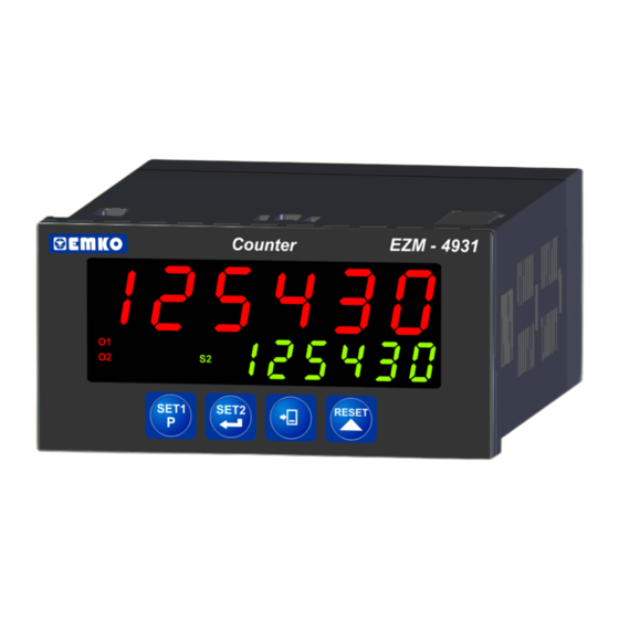
EZM-4931 96 x 48 DIN 1/8
Incremental Encoder Input Programmable
Counter
- 6 digits Process (PV) and 6 digits Set (SV) Value Display
- Operation with 2 Set Value
- Reset , Pause and ChA-ChB Counting Inputs
- Operation with Automatic and Manual Reset
- NPN/PNP input Types
- x1 / x2 / x4 Phase Shifting Property
- Multiplication Coefficient, Division Coefficient and Point Position
- Parametric , Two point (Low Scale - High Scale) and
Multiplication - Division Coefficient
Reading Adjustment
- RS-232 Serial Communication with Modbus RTU Protocol
- Input Frequency Max. 200kHz
- Max. Input Frequency Selection
Instruction Manual. ENG EZM-4931 00 V00 01/11
Advertisement
Table of Contents

Related Manuals for EMKO EZM-4931 Series


Summary of Contents for EMKO EZM-4931 Series
- Page 1 EZM-4931 96 x 48 DIN 1/8 Incremental Encoder Input Programmable Counter - 6 digits Process (PV) and 6 digits Set (SV) Value Display - Operation with 2 Set Value - Reset , Pause and ChA-ChB Counting Inputs - Operation with Automatic and Manual Reset - NPN/PNP input Types - x1 / x2 / x4 Phase Shifting Property - Multiplication Coefficient, Division Coefficient and Point Position...
- Page 2 ABOUT INSTRUCTION MANUAL Instruction manual of EZM-4931 Programmable Counter consists of two main sections. Explanation of these sections are below. Also, there are other sections which include order information and technical specifications of the device. All titles and page numbers in instruction manual are in “CONTENTS”...
-
Page 3: Table Of Contents
CONTENTS 1.PREFACE........................Page 5 1.1 GENERAL SPECIFICATIONS 1.2 ORDERING INFORMATION 1.3 WARRANTY 1.4 MAINTENANCE 2.INSTALLATION......................Page 7 2.1 GENERAL DESCRIPTION 2.2 DIMENSIONS 2.3 PANEL CUT-OUT 2.4 ENVIRONMENTAL RATINGS 2.5 PANEL MOUNTING 2.6 INSTALLATION FIXING CLAMP 2.7 REMOVING FROM THE PANEL 3.ELECTRICAL WIRINGS................... - Page 4 EU DECLARATION OF CONFORMITY Manufacturer’s Name : EMKO ELEKTRONIK A.S. Manufacturer’s Address : DOSAB, Karanfil Sk., No:6, 16369 Bursa, TURKEY The manufacturer hereby declares that the product: Product Name : Programmable Counter Type Number : EZM-4931 Product Category : Electrical equipment for measurement, control and...
-
Page 5: Preface
1.Preface EZM Series Programmable Counter can be used in package machines, production and quality control rollers, in cutting and processing machine of glass, plastic, marble, sheet, iron, fabric all measuring and controlling of dimension, count, total c unt, speed, cycle, productivity, time and can be adapted easily to all mechanical construction and automation system. -
Page 6: Ordering Information
Symbol means Vac and Vdc 1.3 Warranty EMKO Elektronik warrants that the equipment delivered is free from defects in material and workmanship. This warranty is provided for a period of two years. The warranty period starts from the delivery date. This warranty is in force if duty and responsibilities which are determined in warranty document and instruction manual performs by the customer completely. -
Page 7: Installation
2.Installation Before beginning installation of this product, please read the instruction manual and warnings below carefully. In package , - One piece unit - Two pieces mounting clamps - One piece instruction manual A visual inspection of this product for possible damage occured during shipment is recommended before installation. -
Page 8: General Description
2.1 General Description Mounting Clamp Product Label Front Panel IP65 protection Panel surface NEMA 4X (maximum thickness 15 mm / 0.59 inch) 2.2 Dimensions Maksimum 15mm / 0.59 inch EZM-4931 Counter SET1 SET2 RESET 96mm / 3.78 inch 10.5 ± 1 mm / 0.41 inch 76 mm / 2.99 inch... -
Page 9: Panel Cut-Out
2.3 Panel Cut-Out 129 mm / 5.08 inch (min) 92mm / 3.62 inch... -
Page 10: Environmental Ratings
2.4 Environmental Ratings 2.4 Environmental Ratings Operating Conditions Operating Conditions Operating Temperature Operating Temperature : 0 to 50 °C : 0 to 50 °C Max. Operating Humidity : 90% Rh (non-condensing) Max. Operating Humidity : 90% Rh (non-condensing) Altitude Altitude : Up to 2000m. -
Page 11: Installation Fixing Clamp
2.6 Installation Fixing Clamp The unit is designed for panel mounting. 1-Insert the unit in the panel cut- out from the front side. 2- Insert the mounting clamps to the holes that located top and bottom sides of device and screw up the fixing screws until the unit completely immobile within the panel... -
Page 12: Electrical Wirings
3.Electrical Wirings You must ensure that the device is correctly configured for your application. Incorrect configuration could result in damage to the process being controlled, and/or personal injury. It is your responsibility, as the installer, to ensure that the configuration is correct. Parameters of the device has factory default values. -
Page 13: Electrical Wiring Diagram
3.2 Electrical Wiring Diagram Electrical wiring of the device must be the same as ‘Electrical Wiring Diagram’ below to prevent damage to the process being controlled and personnel injury. 5A@250V 5A@250V P/N : EZM-4931 1 2 3 4 5 6 7 8 9 10 11 12 13 14 15 Relay or SSR RS-232 Outputs... -
Page 14: View Of Device Label
3.3 View of Device Label Device Label for 230V Supply Voltage Input and Relay Outputs P/N: EZM-4931 RS-232 Output 2 Output 1 230 V -%15;+%10 Communication 5A@250V 5A@250V 50/60 Hz - 6VA 11 12 13 14 15 Device Label for 24V Supply Voltage Input and Relay Outputs P/N: EZM-4931... -
Page 15: Connection Of Device Supply Voltage Input
3.4 Connection of Device Supply Voltage Input Connection of Universal Connection of Universal Supply Voltage Input Supply Voltage Input External External Fuse Fuse (1 A (1 A Power Power Supply Supply Switch Switch Supply Voltage Supply Voltage 115V , 230 V (-%15;+%10) 50/60Hz (-%15;+%10) 50/60 Hz Note-1 :... -
Page 16: Counting Input Connection
3.5 Counting Input Connection 3.5.1 Incremental Encoder & Switch Connection PNP type operation INCREMENTAL ENCODER NOTE-1 NPN type operation INCREMENTAL ENCODER NOTE-1 NOTE-1 : Reset and Pause inputs have protection time against electrical contact debounce. Protection time can be set with parameter (2 - 50 msec.). -
Page 17: Galvanic Isolation Test Values Of Ezm-4931 Programmable Counter
3.6 Galvanic Isolation Test Values of EZM-4931 Programmable Counter 2000V ( for EZM-4931.1... and EZM-4931.2... ) Supply Voltage Input 2000V 2000V Relay-1 Output 2000V 2000V Relay-2 Output 2000V Optional SSR Driver 2000V Optional SSR Driver 2000V RS-232 Serial Communication 2000V or 5V Sensor Supply Voltage... - Page 18 Galvanic Isolation Test Values For 24 V Power Supply Supply Voltage Input 2000V 2000V Relay-1 Output 2000V 2000V Relay-2 Output Optional SSR Driver Optional SSR Driver RS-232 Serial Communication or 5V Sensor Supply Voltage Digital Inputs...
- Page 19 3.7 Output Connections 3.7.1 Relay-1 Output Connection Device T Fuse Last Control Element (Contactor) Fuse Load Fuses must be selected according to the applications. 3.7.2 SSR Driver-1 Output Connection Device Last Control Element (SSR) Fuse Maks. 10mA Load Fuses must be selected according to the applications.
- Page 20 3.7.3 Relay-2 Output Connection Device T Fuse Last Control Element (Contactor) Fuse Load Fuses must be selected according to the applications. 3.7.4 SSR Driver-2 Output Connection Device Last Control Element (SSR) Fuse Maks. 10mA Load Fuses must be selected according to the applications.
-
Page 21: Definition Of Front Panel And Accessing To The Set Parameters
4. Definition of Front Panel and Accessing to the Set Parameters 4.1 Definition of Front Panel Counter EZM-4931 Displays Actual Value and Parameter Led indication of O1 / O2 : OUT1 / OUT2 Displays SET1, output is active SET2 value and Parameters SET1 SET2... -
Page 22: Power On Observation Of Ezm - 4931 Programmable Counter And Software Revision On The Display
4.2 Power On Observation of EZM - 4931 Programmable Counter and Software Revision on the Display When power is applied to the device, software revision number of the controller is momentarily illuminated on actual value display. Then operation screen is observed. When power on, view of the screen is shown below: Counter EZM-4931... -
Page 23: Adjustment Of Set Value
4.3 Adjustment of SET Value Changing SET1 value. Operation SET1 Screen Screen SET1 SET2 RESET SET1 SET2 RESET When shift button is Press SET1 button to exit When shift button is pressed, 6th digit of SET1 without saving Set value. pressed, 5th digit of SET1 value starts to flash. -
Page 24: Resetting Count Value
4.4 Resetting the Count Value Operation Operation Screen Screen SET1 SET2 RESET SET1 SET2 RESET When RESET button is pressed, Actual Value becomes the Reset-Offset Value. Reset and Set Protection parameter is then Count Value can not be reset. For details, refer to parameters section. RESET operation can be realized by Reset button or applying signal to the RESET input. -
Page 25: Accessing To The Program Parameters
4.5 Accessing to the Program Parameters In this section Accessing to the Program parameters process is shown. For details on parameters refer to PROGRAM PARAMETERS section. Operation Screen Password Screen SET1 SET2 RESET SET1 SET2 RESET When PROG button is pressed Enter password The most significant digit of for 3 seconds, password screen... - Page 26 Max. Input Frequency You can change the p a r a m e t e r w i t h INCREMENT button, SET1 SET2 RESET save it to the memory and p a s s t o t h e n e x t Press PROG button to exit parameter with ENTER from programming section...
- Page 27 Output Functions You can change the p a r a m e t e r w i t h INCREMENT button, SET1 SET2 RESET save it to the memory and p a s s t o t h e n e x t Press PROG button to exit parameter with ENTER from programming section...
-
Page 28: Program Parameters
8. PARAMETRELER 5. Program Parameters Input Types and Functions. ( Default = 2 ) MODBUS ADDRESS:40001. x1 Phase Shifting (for incremental encoders) Upcount on rising edge of Ch-A input when Ch-B is at 0 Downcount on rising edge of Ch-A input when Ch-B is at 1 Encoder is travelling Ch-A in the Reverse Direction... - Page 29 x4 Phase Shifting (for incremental encoders) Upcount on rising edge of Ch-A when Ch-B is at 0 Downcount on falling edge of Ch-A when Ch-B is at 0 Downcount on rising edge of Ch-A when Ch-B is at 1 Upcount on falling edge of Ch-A when Ch-B is at 1 Downcount on rising edge of Ch-B when Ch-A is at 0 Upcount on falling edge of Ch-B when Ch-A is at 0 Upcount on rising edge of Ch-B when Ch-A is at 1...
- Page 30 Filter time for Reset and Pause Input ( Default = 50 ) MODBUS ADDRESS:40003. It is used to protect against the electrical contact debounce or the signal that is less than the determined pulse time. It can be adjusted from milisecond.
- Page 31 Reset and Set protection (For accessing from front panle) ( Default = 0 ) MODBUS ADDRESS:40007. There is no Reset and Set protection. Only RESET button protection is active. Actual value can not be reset by Reset button. Actual value can be reset only reset input is active. SET1 and SET2 can not be changed.
- Page 32 Encoder Type ( Default = 1000 ) MODBUS ADDRESS:40012. Number of pulse of Encoder is used pulse. NOTE-1 It can be adjusted from pulse/rnd. Pitch ( Default = 1000 ) MODBUS ADDRESS:40013. Encoder’s amount of progress on an round. NOTE-1 It can be adjusted from mm/rnd.
- Page 33 Output Functions ( Default = 1 ) MODBUS ADDRESS:40022. Manual Reset-0. Device continues to count till manual reset is applied. Counting direction : 0 P (Upcount) Reset Set2 Set1 Reset Offset Output-1 Output-2 Device continues to count till manual reset is applied. When Manual Reset happens, count value becomes Reset Offset value.Outputs are not active in this parameter.
- Page 34 Manual Reset-1. Device continues to count till manual reset is applied. (Output PulseTime is not considered) Counting direction : 0 P (Upcount) Reset Set2 Set1 Reset Offset Output-1 Output-1 Output-2 When count value reaches to SET1 value, Output-1 becomes active. If Output-1 pulse time , Output-1 does not change condition until manual reset input is active.
- Page 35 Manual Reset-2. (Output-2 Pulse Time is not considered) Counting direction : 0 P (Upcount) Reset Set2 Set1 Reset Offset Output-1 Output-1 Output-2 When the count value reaches to SET1 value, Output-1 becomes active. If Output-1 pulse time , Output-1 does not change position until manual reset input is active.
- Page 36 Manual Reset-3. Counting continues until Manual Reset input is active. Counting direction : 0 P (Upcount) Reset Set2 Set1 Reset Offset Output-1 Output-1 Output-2 Output-1 Output-2 When the count value reaches to SET1 value, Output-1 becomes active. If Output-1 Pulse Time is not 0, Output-1 changes position at the end of the pulse time.If Output-1 Pulse Time it changes position until Manual Reset input is active or according to...
- Page 37 When the count value reaches to SET1 value, Output-1 becomes active. If Output-1 pulse time is not 0, Output-1 changes position at the end of the pulse time.If Output-1 Pulse Time it changes position until Manual Reset input is active or according to Output-2.
- Page 38 When the count value reaches to SET1 value, Output-1 becomes active. Output-1 does not change position until manual reset input is active. Output-1 pulse time is not considered. When the count value reaches to value, Output-2 becomes active. Output-2 does not change position until manual reset input is active.
- Page 39 When the count value reaches to SET1 value, Output-1 becomes active.Output-1 does not change, condition until manual reset input is active or Count value becomes equal to Reset Offset value. Output-1 pulse time is not considered. When the count value reaches to value,Output-2 becomes active.Output-2 does not change, condition until manual reset input is active or Count value becomes equal to Reset Offset value.
- Page 40 When count value reaches to SET1 value, Output-1 becomes active. If Output-1 pulse time , Output-1 does not change condition until manual reset input is active.If Output-1 pulse time is not 0, at the end of the pulse time Output-1 becomes inactive.
- Page 41 When count value reaches to SET1 value, Output-1 becomes active. If Output-1 pulse time , Output-1 does not change condition until manual reset input is active.If Output-1 pulse time is not 0, at the end of the pulse time Output-1 becomes inactive.
- Page 42 Counting Direction : P 0 (Downcount) Reset Set2 Reset Offset Set1 Output-1 Output-1 Output-2 Output-1 Output-2 When the count value reaches to SET1 value, Output-1 becomes active. If Output-1 pulse time is not 0, Output-1 changes position at the end of the pulse time.If Output-1 Pulse Time it changes position until Manual Reset input is active or according to Output-2 position.
- Page 43 Automatic Reset-2. Counting direction : 0 P (Upcount) Reset Set2 Set1 Reset Offset Output-1 Output-1 Output-2 Reset Set2 Set1 Reset Offset Output-1 Output-1 Output-2 When the count value reaches to SET1, Output-1 becomes active. If Output-1 pulse time is not 0, Output-1 changes position at the end of the pulse time.
- Page 44 Counting direction : P 0 (Downcount) Reset Set2 Reset Offset Set1 Output-1 Output-1 Output-1 Reset Set2 Reset Offset Set1 Output-1 Output-1 Output-2 When the count value reaches to SET1, Output-1 becomes active. If Output-1 pulse time is not 0, Output-1 changes position at the end of the pulse time.
- Page 45 Automatic Reset-3. Counting direction : 0 P (Upcount) Reset Set2 Set1 Reset Offset Output-1 Output-1 Output-2 Reset Set2 Set1 Reset Offset Output-1 Output-1 Output-2 When the count value reaches to SET1, Output-1 becomes active.If Output-1 pulse time is not 0, Output-1 changes position at the end of the pulse time.
- Page 46 Counting direction : P 0 (Downcount) Reset Set2 Reset Offset Set1 Output-1 Output-1 Output-2 Reset Set2 Reset Offset Set1 Output-1 Output-1 Output-2 When the count value reaches to SET1, Output-1 becomes active. If Output-1 pulse time is not 0, Output-1 changes position at the end of the pulse time.
- Page 47 Automatic Reset-4. Counting direction : 0 P (Upcount) Reset Set2 Set1 Reset Offset Output-1 Output-1 Output-2 Reset Set2 Set1 Reset Offset Output-1 Output-1 Output-2 When the count value reaches to SET1, Output-1 becomes active. If Output-1 pulse time is not 0, Output-1 changes position at the end of the pulse time.
- Page 48 Counting Direction : P 0 (Downcount) Reset Set2 Reset Offset Set1 Output-1 Output-1 Output-2 Reset Set2 Reset Offset Set1 Output-1 Output-1 Output-2 When the count value reaches to SET1, Output-1 becomes active. If Output-1 pulse time is not 0, Output-1 changes position at the end of the pulse time.If Output-1 Pulse Time , it changes position until Manual Reset input is active or according to...
- Page 49 Automatic Reset-5. Pulse times is not considered. Counting direction : 0 P (Upcount) Reset Set2 Set1 Reset Offset Output-1 Output-2 If count value is equal or greater than SET1 value, then Output-1 becomes active. Output-1 pulse time is not considered. If count value is equal or greater than SET2 value, then Output-2 becomes active.
- Page 50 Output-1 Operation Form ( Default = 0 ) MODBUS ADDRESS:40023. Output-1 Normally non-energised. Output-1 Normally energised. Output-2 Operation Form ( Default = 0 ) MODBUS ADDRESS:40024. Output-2 Normally non-energised. Output-2 Normally energised. Output-1 Pulse Time ( Default = 0000.00 ) MODBUS ADDRESS:40025. It determines how long Output-1 will be active.
- Page 51 Saving Count Value (Power down back-up) ( Default = 0 ) MODBUS ADDRESS:40032. Count value is saved to memory when power is disconnected and restored on power up. Count value is not saved to memory when power is disconnected. When power up is shown on the screen.
-
Page 52: Read Input Register Command
Return to Factory Settings ( Default = 0 ) MODBUS ADDRESS:40037. Restore all settings to factory default. This parameter has a special password. Program Password ( Default = 0 ) MODBUS ADDRESS:40038. It is used for accessing to the program parameters. It can be adjusted from If it is , there is no password protection while accessing to the... -
Page 53: Failure Messages In Ezm-4931 Programmable Counter
7. Failure Messages in EZM-4931 Programmable Counter 1-If the password is not , user can access to the parameters without entering the password and by pressing ENTER button. User can see all parameters except for programming password parameter but user can not do any changes in parameters. -
Page 54: Specifications
8. Specifications Device Type : Programmable Counter. Housing & Mounting : 96mm x 48mm x 86.5mm 1/8 DIN 43700 plastic housing. For panel mounting. Panel cut-out is 92x46mm. Protection Class : NEMA 4X (IP65 at front, IP20 at rear). Weight : Approximately 0.29 Kg.
Need help?
Do you have a question about the EZM-4931 Series and is the answer not in the manual?
Questions and answers
Hello, I have bought a new EZM-4931 counter, but it is configured with a password. I can't find a way of resetting the password so that I can configure it again. I **** asking for help from you to be able to return to factory sitting, so that I can do my own configuration of the counter.
To reset the password on the EMKO EZM-4931 counter and return it to factory settings, use the Return to Factory Settings parameter at MODBUS ADDRESS:40037. This action restores all settings, including the password, to default. Note that this parameter requires a special password to execute.
This answer is automatically generated