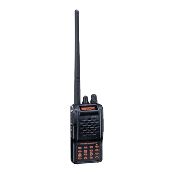
Vertex Standard VXA-150 Introduction
Hide thumbs
Also See for VXA-150:
- Operating manual (40 pages) ,
- Service manual (32 pages) ,
- Specifications (2 pages)
Table of Contents
Advertisement
Quick Links
The VXA-150 is carefully aligned at the factory for the specified performance across
the Aircraft and Weather bands. Realignment should therefore not be necessary except
in the event of a component failure.
The following procedures cover the adjustments that are not normally required once
the transceiver has left the factory. However, if damage occurs and some parts
subsequently are replaced, realignment may be required. If a sudden problem occurs
during normal operation, it is likely due to component failure; realignment should not
be done until after the faulty component has been replaced.
We recommend that servicing be performed only by authorized Vertex Standard
service technicians who are experienced with the circuitry and fully equipped for
repair and alignment. If a fault is suspected, contact the dealer from whom the
transceiver was purchased for instructions regarding repair. Under no circumstances
should any alignment be attempted unless the normal function and operation of the
transceiver are clearly understood, the cause of the malfunction has been clearly
pinpointed and any faulty components replaced, and realignment determined to be
absolutely necessary. Problems caused by unauthorized attempts at realignment are
not covered by the warranty policy
Vertex Standard reserves the right to change circuits and alignment procedures, in the
interest of improved performance, without notifying owners.
The following test equipment (and familiarity with its use) is necessary for complete
realignment. While most steps do not require all of the equipment listed, the
interactions of some adjustments may require that more complex adjustments be
performed afterwards. Do not attempt to perform only a signal step unless it is clearly
isolated electrically from all other steps. Have all test equipment ready before
beginning, and follow all of the steps in a section in the order presented.
Correction of problems caused by misalignment resulting from use of improper test
equipment is not covered under the warranty policy.
Note: Signal levels in dB refereed to in this procedure are based on 0 dBµ = 0.5 µV
(closed circuit).
Introduction
Introduction
Introduction
Introduction
1
VXA-150
Alignment
Vertex Standard Co., Ltd.
Advertisement
Table of Contents

Subscribe to Our Youtube Channel
Related Manuals for Vertex Standard VXA-150


Summary of Contents for Vertex Standard VXA-150
- Page 1 Introduction Introduction Introduction The VXA-150 is carefully aligned at the factory for the specified performance across the Aircraft and Weather bands. Realignment should therefore not be necessary except in the event of a component failure. The following procedures cover the adjustments that are not normally required once the transceiver has left the factory.
- Page 2 Connect the wattmeter, dummy load and frequency counter connected to the antenna jack, and tune the transceiver to 120.000 MHz. Transmit, and adjust TC1001 on the RF Unit, if necessary, so the counter frequency is 120.000 MHz (±100 Hz). Vertex Standard Co., Ltd.
- Page 3 Inject a –9 dBµ (0.35 µV) RF signal (with a standard modulation: 30 % AM modulation @ 1 kHz), then press the CHANNEL selector knob twice . Now rotate the CHANNEL selector knob to select the next setting. Vertex Standard Co., Ltd.
- Page 4 If you are unable to gain control of the transceiver (or if you want to clear all memories and settings to their factory defaults), press and holding the MONITOR button and PTT switch while turning the transceiver on. Vertex Standard Co., Ltd.
Need help?
Do you have a question about the VXA-150 and is the answer not in the manual?
Questions and answers