Table of Contents
Advertisement
Quick Links
USER
MANUAL
VC-212RT
Parts Tester
The VC-212RT allows you to diagnose the operational
performance of a 12 and 24 volt alternator regulator.
VC-212RT regulator tester is a very useful and
easy to use device, used by car garages, diagnostic stations,
authorised service stations and rebuilders.
This small and light weighted tester was developed
according to the requirements of service stations and
works without any additional testing or measuring devises.
ENGLISH
VERSION 2018
www.motoplat.nl
Advertisement
Table of Contents

Related Manuals for Motoplat VC-212RT


Summary of Contents for Motoplat VC-212RT
- Page 1 USER MANUAL VC-212RT Parts Tester The VC-212RT allows you to diagnose the operational performance of a 12 and 24 volt alternator regulator. VC-212RT regulator tester is a very useful and easy to use device, used by car garages, diagnostic stations, authorised service stations and rebuilders.
- Page 2 People who start using this product should review carefully this instruction manual, or have had a training from a qualified person. The use of electrical equipment is entirely at your own risk and Motoplat® is under no circumstances responsible for any incidental, consequential or special damages of any kind whatsoever, including but not limited to lost profits arising from or in any way connected with the use of the automated test equipment or this manual.
-
Page 3: Table Of Contents
Motoplat ® Index 1 General Information General information about the Motoplat VC-212RT tester 2 Specifications and Installation Technical specifications Back panel Front panel: Buttons Front panel: Connections 3 Regulator Test Displayed operation modes Button meanings and results Stator On/Off button... -
Page 4: General Information
Motoplat ® Section 1 – General information 1.0 General information about Motoplat VC-212RT tester: • Supports all control interfaces for modern voltage regulator such as LIN/BSS and PWM • Automatic detection of a regulator load control of type, А or В. -
Page 5: Specifications And Installation
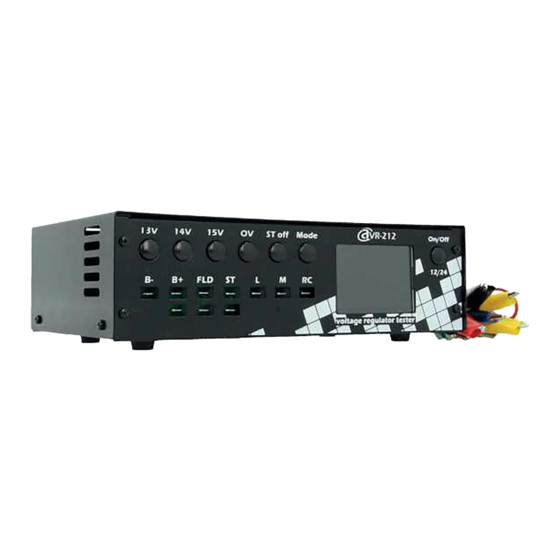
Motoplat ® Section 2 – Specifications and Installation 2.0 Technical specifications: General Voltage (V) 12/24 Dimensions (MM) 252*158*79 Weight (KG) 1,71 (net. weight) 2.1 Back panel: Description Cable connection Fuse (15A / 125 VAC) Check if the fuse is tightened proparly. -
Page 6: Front Panel: Buttons
Motoplat ® 2.2 Front panel : Buttons Description Explanation 13V / 14V / 15V simulation of commands for setting the corresponding regulator voltage at the RC output. Operable in all modes excluding LAMP. Simulation of an overvoltage. Press again to turn off this mode. -
Page 7: Regulator Test
Motoplat ® Section 2 – Regulator Test 3.0 Displayed operation modes: The following device operating modes can be selected by pressing button MODE: LAMP mode C mode (Nissan) P-D mode (Mazda, KIA) RLO mode (Toyota) SIG mode (Ford,Landrover and Motorcraft) -
Page 8: Button Meanings And Results
Motoplat ® 3.1 Button meanings and results: When simulating commands for setting regulator voltage by pressing buttons 13 V, 14 V and 15 V, the following messages are displayed respectively: Result: the regulator should react to the voltage commands. 3.2 Stator On/Off button:... -
Page 9: Lamp
Motoplat ® 3.4 Lamp: The following icons are displayed for the L (LAMP) input: Not charging: Charging Result: Battery lamp ON is NOT charging mode and Battery lamp OFF is charging mode. 3.5 DFM or Feedback to ECU: Signal frequency and duty cycle at the input M (DFM) are displayed as follows: Result: should show a percentage and/or frequency 3.6 Field:... -
Page 10: Through The Voltage Regulator
Motoplat ® 3.7 Through the voltage regulator: DC- switching (circuit A): DC+ switching (circuit B): Result: regulator should charge 3.8 COM LIN/BSS: If there is no connection to the regulator in the СОМ mode, a “No connection” message is displayed: When LIN or BSS protocols are detected, the following messages are displayed: respectively followed by a regulator identifier. - Page 11 Motoplat ® Reference connection of the regulator to the tester: COM mode Protocol LIN, type A, identifier 33. The regulator operates at three speeds. DFM from the regulator, 9% rotor load Mechanical error (no stator signal) Switching mode of the field...
-
Page 12: Contact Information
Contact Information MOTOPLAT CV Stichtse Kade 47c 1244NV ‘s-Graveland, The Netherlands + 31 (0)35 656 3180 info@motoplat.nl www.motoplat.nl www.motoplat.nl...
Need help?
Do you have a question about the VC-212RT and is the answer not in the manual?
Questions and answers