Table of Contents
Advertisement
Quick Links
VC-3.1
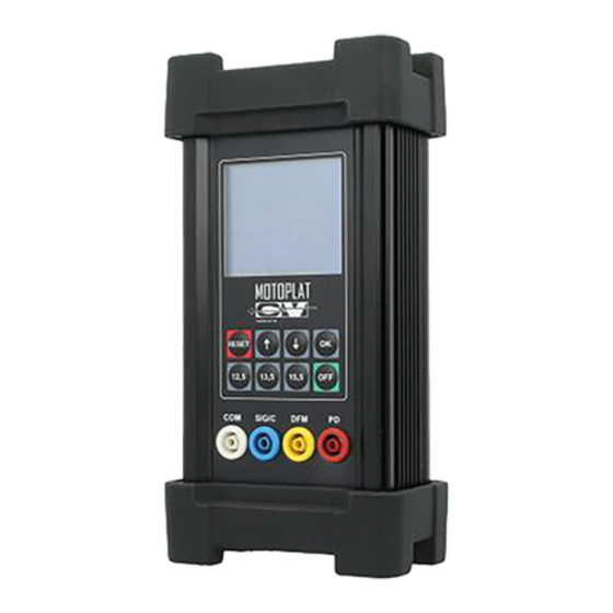
All-in-one handheld tester
The VC-3.1 is a sturdy looking handheld tester and analyzer
that can stand rough handling. Combining all functions and
possibilities of our other handheld testers, the VC-3.1 is
unique in its kind. Detailed specifications are outlined below.
Detailed specifications are outlined below.
Specifications
o
On-car testing
o
Operates on conventional test equipment
o
Static testing
o
Built-in 19 volt lithium ion battery pack
o
User-friendly
USER
MANUAL
ENGLISH
VERSION 2020
www.motoplat.nl
Advertisement
Table of Contents

Related Manuals for Motoplat VC-3.1


Summary of Contents for Motoplat VC-3.1
- Page 1 MANUAL VC-3.1 All-in-one handheld tester The VC-3.1 is a sturdy looking handheld tester and analyzer that can stand rough handling. Combining all functions and possibilities of our other handheld testers, the VC-3.1 is unique in its kind. Detailed specifications are outlined below.
- Page 2 People who start using this product should review carefully this instruction manual, or have had a training from a qualified person. The use of electrical equipment is entirely at your own risk and Motoplat® is under no circumstances re- sponsible for any incidental, consequential or special damages of any kind whatsoever, including but not limited to lost profits arising from or in any way connected with the use of the automated test equipment or this manual.
-
Page 3: Table Of Contents
Motoplat ® Index 1 General Information General information about the Motoplat VC-3.1 alternator tester 2 Installation Charging Software version check (Re-)placing micro SD card 3 Instructions Button descriptions Plugs descriptions 4 Systems STATIC TEST ON-CAR AND TEST BENCH VEHICLE ALT TEST... -
Page 4: General Information
• User-friendly Improvements The VC-3.1 is the first in our range of handheld testers, equipped with a full color screen and a complete new button pad. These major upgrades improve user comfort and the efficiency of testing. The button pad makes it much easier to scroll through the testing modes and during the test, to select the control capabilities (e.g., the voltage). -
Page 5: Installation
The software version will appear on the screen. 2.2 (Re-)placing micro SD card The VC-3.1 alternator tester is equipped with a micro SD card that contains the Motoplat VC-3.1 software. To place or replace the micro SD card, follow the steps below: •... -
Page 6: Instructions
Motoplat ® Section 3 – Instructions 3.0 Button descriptions: RESET Exit/Reset from current function Tester will start up automatically and return to the main menu ↑ Arrow up Selection up ↓Arrow down Selection down Confirmation 12,5V Voltage set point button... -
Page 7: Systems
Motoplat ® Section 4 – Systems 4.0 STATIC TEST: The static test can identify regulator protocols and ID codes of alternators/regulators using LIN, BSS or a Lamp fuction. Using the internal battery source, voltage will be applied through the black and red test cables to the alternators/regulator. -
Page 8: Vehicle Alt Test
4.3 TEST BENCH TEST: Full control of alternator on the test bench LIN/BSS and Lamp Using the VC-3.1 in static test or protocol checking mode only. The main power switch must be set to „ON” Only ‘Test Bench Test’ will be available in the main menu. -
Page 9: Ecu Ford Pwm Test
Motoplat ® 4.4 ECU FORD PWM TEST: PWM ECU system analysis for Ford Focus, Mondeo,all 6G regulators. Requested voltage by the car PCM is shown in lower left corner, DFM signal going from alternator to the car PCM- shown in the center of the screen in % and actual voltage is shown in down right corner. -
Page 10: Ecu Alt Ford Pwm Test
Motoplat ® 4.6 ECU OPEL/ GM PWM/RVC TEST: PWM Opel/GM signal analysis PWM/RVC system requested voltage by the car PCM is shown in lower left corner, DFM signal going from alternator to the car PCM- shown in the center of the screen in % and actual voltage is shown in lower right corner. -
Page 11: Pd Mazda Alt Test
Motoplat ® 4.8 PD MAZDA ALT TEST: Full control of PD Mazda type alternator on test bench Only the ‘D’ terminal is connected from tester to the regulator. P is not connected to the tester! (P is a phase connection and should always measure half the charging voltage.) -
Page 12: Dfm
Motoplat ® 4.6 DFM: DFM signal analisys Load information in % is a signal from regulator to ECU. Page 12... - Page 13 Contact Information MOTOPLAT CV Stichtse Kade 47c 1244NV ‘s-Graveland, The Netherlands + 31 (0)35 656 3180 info@motoplat.nl www.motoplat.nl www.motoplat.nl...
Need help?
Do you have a question about the VC-3.1 and is the answer not in the manual?
Questions and answers