Table of Contents
Advertisement
Quick Links
UIC00A
USB ICSP PIC PROGRAMMER
User's Manual
V1.8
Oct 2009
Information contained in this publication regarding device applications and the like is intended through suggestion only and may
be superseded by updates. It is your responsibility to ensure that your application meets with your specifications. No
representation or warranty is given and no liability is assumed by Cytron Technologies Incorporated with respect to the accuracy
or use of such information, or infringement of patents or other intellectual property rights arising from such use or otherwise. Use
of Cytron Technologies's products as critical components in life support systems is not authorized except with express written
approval by Cytron Technologies. No licenses are conveyed, implicitly or otherwise, under any intellectual property rights.
Advertisement
Table of Contents

Subscribe to Our Youtube Channel
Related Manuals for Cytron Technologies UIC00A


Summary of Contents for Cytron Technologies UIC00A
- Page 1 It is your responsibility to ensure that your application meets with your specifications. No representation or warranty is given and no liability is assumed by Cytron Technologies Incorporated with respect to the accuracy or use of such information, or infringement of patents or other intellectual property rights arising from such use or otherwise. Use of Cytron Technologies’s products as critical components in life support systems is not authorized except with express written...
-
Page 2: Table Of Contents
7.1 Using PICkit 2 Programmer Software 7.2 Using UIC00A 7.2.1 Using UIC00A with application circuit (development board) 7.2.2 Using UIC00A with UIC-S (optional, buy separately) 7.3 Troubleshooting 8. Warranty (6 months) Created by Cytron Technologies Sdn. Bhd. – All Right Reserved... -
Page 3: Introduction And Overview
• Optional socket (UIC-S) to program 18 pins, 28 pins and 40 pins PIC microcontroller. *UIC00A has been tested on several editions of Windows Vista. If user found it is not compatible, we will offer money back guarantee (need to be shipped back within 3 days from receiving date, shipping is not included). -
Page 4: Packaging List
2. 1 x mini USB cable 3. 1 x rainbow cable (programming cable) 4. 1 x Software Installation and User’s Manual CD 5. 1 x UIC-S socket board (optional, buy separately from Cytron website) Created by Cytron Technologies Sdn. Bhd. – All Rights Reserved... -
Page 5: Supported Pic
ROBOT . HEAD to TOE Product User’s Manual – UIC00A 3. SUPPORTED PIC UIC00A is compatible with PICkit 2 programmer software. It has been tested to load program using UIC-S socket board. Below are the PIC models that being tested using UIC00A:... - Page 6 PIC Microcontroller: Stand alone mode. Note: For those PIC models not listed in the table (but supported in PICkit 2 list) are not fully tested by Cytron Technologies with UIC00A. User is advised to ensure its compatibility. Note: “Use Vpp First Programming Entry” is not supported by UIC00A. Therefore,...
-
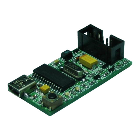
Page 7: Board Layout
Green LED at “C” is used to indicate the main power supply of UIC00A. It should ON once USB connection from UIC00A to computer or laptop is ready. Red LED at “D” is used to indicate busy function such as UIC00A is in program mode or is alerting that a function is in progress. -
Page 8: Installation (Hardware)
3. Continue to software installation if this is the first time usage. Refer to section 6 for software installation guide. 4. Connect one side of programming cable to box header of UIC00A and the other side to box header of development board (target device) to be program. -
Page 9: Using Uic00A With Uic-S (Optional, Buy Separately)
3. Continue to software installation if this is the first time usage. Refer to section 6 for software installation guide. 4. Connect one side of programming cable to box header of UIC00A and the other side to box header of UIC-S board. -
Page 10: Plugging The Microcontroller
40-pin Microcontroller • Plug in the microcontroller at the ZIF socket and select 40 pins at label “28/40 Pins” using mini jumper as shown below. Pin 1 Select to 28/40 pins Created by Cytron Technologies Sdn. Bhd. – All Rights Reserved... - Page 11 • Plug in the microcontroller at the upper portion of the ZIF socket and select 28 pins at label “28/40 Pins” using mini jumper as shown below. Pin 1 Select to 28/40 pins Created by Cytron Technologies Sdn. Bhd. – All Rights Reserved...
- Page 12 • Plug in the microcontroller at the lower portion of the ZIF socket and select 18 pins at label “18 Pins” using mini jumper as shown below. Pin 1 Select to 18 pins Created by Cytron Technologies Sdn. Bhd. – All Rights Reserved...
-
Page 13: Installation (Software)
Product User’s Manual – UIC00A 6. INSTALLATION (SOFTWARE) Since UIC00A is compatible with PICkit 2, thus PICkit 2 programming software should be installed. With the help of pictures and some simple instruction, following section will guide to install the PICkit 2 programming software. - Page 14 Follow steps below to setup Microchip PICkit2 Programmer after launched the setup file. 1. Click next. 2. The following window concerns the installation folder. Click Browse if you want to change the default destination. Assuming change, click on Next. Created by Cytron Technologies Sdn. Bhd. – All Rights Reserved...
- Page 15 3. Click next to start the installation of the PICkit 2 programming software. 4. The following license agreement window will appears. In order to proceed with the installation, read the conditions, select the option I Agree and click on Next. Created by Cytron Technologies Sdn. Bhd. – All Rights Reserved...
- Page 16 ROBOT . HEAD to TOE Product User’s Manual – UIC00A 5. Wait for a while. PICkit 2 is being installed to PC. 6. After complete installation, click Close to exit. Created by Cytron Technologies Sdn. Bhd. – All Rights Reserved...
-
Page 17: Getting Started
7. GETTING STARTED 7.1 Using PICkit 2 Programmer Software After installing hardware and software in previous section, UIC00A is ready to be used with PICkit 2 programming software. This section gives instruction on how to get started with UIC00A. With the help of pictures and some simple instruction, following section illustrates the steps using UIC00A. - Page 18 • If device is successfully detected, the device name will appeared at “Device Configuration” area. 3. UIC00A can supply power to the target device. However, users are advised to power the target device externally to prevent this programmer exceed from 150mA current limit.
- Page 19 ROBOT . HEAD to TOE Product User’s Manual – UIC00A Caution: USB port current limit is 150mA. If the target and UIC00A exceed this current limit, the UIC00A board might be damaged. The target board should be powered externally. If the target device is powered externally, please DONOT connect V (5V) of UIC00A to target PIC, only one power supply should be connected to target PIC.
- Page 20 Write. The PIC will be erased and programmed with the new Hex code imported. The operation status will display on the Status Bar and the status bar will turn to GREEN if writing is successful. Created by Cytron Technologies Sdn. Bhd. – All Rights Reserved...
- Page 21 ROBOT . HEAD to TOE Product User’s Manual – UIC00A 8. Push button (on UIC00A main board) is a special feature to load Hex file into the target device. Push button can be used after Programmer>Write on PICkit Button is checked as figure below: 9.
- Page 22 ROBOT . HEAD to TOE Product User’s Manual – UIC00A 10. Press push button and the Hex file will automatically program into the target device. Created by Cytron Technologies Sdn. Bhd. – All Rights Reserved...
- Page 23 11. Push button allow user to reload the updated hex file into the target device. After convert any changes in the program into Hex file, press push button again and UIC00A will automatically reload the new Hex file, further program into the target device.
- Page 24 By clicking this icon, it will bring up an Import Hex File dialog. 14. After selecting file, Hex code will be written to the target device and UIC00A will monitor the selected file for update. If the file is updated (after compiled), UIC00A will automatically re-imports the Hex file and writes to the target device.
- Page 25 ROBOT . HEAD to TOE Product User’s Manual – UIC00A 15. Old UIC00A’s firmware must updated in order to use with new version of PICkit 2 (2.55 version) software. The PICkit 2 software will prompt user to update the firmware.
- Page 26 • Connect A-type USB connector (one end of USB cable) to USB port at laptop or PC desktop. • Connect the other end of USB cable (mini) to UIC00A USB port. Green LED (Power) will turn on. • Click on “Check Hardware”. When the operation is succeeded, Unit ID and OS Firmware will be displayed as shown in figure below.
- Page 27 ROBOT . HEAD to TOE Product User’s Manual – UIC00A • Click “Download Firmware” to start download new firmware into UIC00A. Wait for around 30 second for the operation to complete. • After downloading process completed, user can use UIC00A programmer as usual.
-
Page 28: Using Uic00A
1) Program a PIC MCU with the MCU on development board which has been shown in section 5.1. 2) Program a PIC MCU in stand alone mode, shown in section 5.2. Created by Cytron Technologies Sdn. Bhd. – All Rights Reserved... -
Page 29: Using Uic00A With Application Circuit (Development Board)
ROBOT . HEAD to TOE Product User’s Manual – UIC00A 7.2.1 Using UIC00A with application circuit (development board) UIC00A can program PIC microcontroller installed in the application circuit using In-Circuit Serial Programming (ICSP). In-Circuit Serial Programming requires five signals: • V –... - Page 30 • The minimum connections from UIC00A to target board or PIC are four. These include Vpp, PGD, PGC and Vss (Gnd). • Thus, the 5V from UIC00A is an optional connection. If user is powering up the target board with external power, this pin is not necessary to connect from UIC00A to target board.
-
Page 31: Using Uic00A With Uic-S (Optional, Buy Separately)
7.2.2 Using UIC00A with UIC-S (optional, buy separately) UIC-S is an optional socket that can be used with UIC00A to program several types of PIC microcontroller. Below are the steps of using the UIC-S and method to connect it to UIC00A: 1. -
Page 32: Troubleshooting
Check MCLR pin of target PIC, there should not be capacitor connected. f. When UIC-S is plug in Green LED at UIC00A is ON but Green LED and UIC-S is not ON. i) UIC00A on board fuse is burned, there might be some place shorted causing this. -
Page 33: Warranty (6 Months)
Warranty does not cover freight cost for both ways. Prepared by Cytron Technologies Sdn. Bhd. 19, Jalan Kebudayaan 1A, Taman Universiti, 81300 Skudai, Johor, Malaysia. Tel: +607-521 3178 Fax: +607-521 1861 URL: www.cytron.com.my Email: support@cytron.com.my sales@cytron.com.my Created by Cytron Technologies Sdn. Bhd. – All Rights Reserved...
Need help?
Do you have a question about the UIC00A and is the answer not in the manual?
Questions and answers