
Related Manuals for Cytron Technologies SHIELD-MD10


Summary of Contents for Cytron Technologies SHIELD-MD10
- Page 1 R OBOT . HEAD to TOE P roduct User’s Manual – S HIELD-MD10 SHIELD-MD10 Cytron 10A Motor Driver Shield User's Manual V1.0 June 2015 Created by Cytron Technologies Sdn. Bhd. – All Right Reserved...
-
Page 2: Table Of Contents
R OBOT . HEAD to TOE P roduct User’s Manual – S HIELD-MD10 Index Introduction Packing List Product Specification and Limitations Board Layout Dimension Hardware Installation Warranty Created by Cytron Technologies Sdn. Bhd. – All Right Reserved... -
Page 3: Introduction
Note: Please note that there will be only Shield MD10 Rev 2.0. There is an improvement made in Shield MD10 Rev 2.0. For Shield MD10 Rev 2.0, "SHIELD-MD10 R2" is labelled at the front and back of the shield like shown in the figure. - Page 4 R OBOT . HEAD to TOE P roduct User’s Manual – S HIELD-MD10 Created by Cytron Technologies Sdn. Bhd. – All Right Reserved...
-
Page 5: Packing List
Please check the parts and components according to the packing lists. If there are any parts missing, please contact us at ales@cytron.com.my immediately. 1. 1 x S HIELD-MD10 shield 2. 2 x m ini jumper Created by Cytron Technologies Sdn. Bhd. – All Right Reserved... -
Page 6: Product Specification And Limitations
I ( Peak Motor Current)* P EAK V (Logic Input-High Level) I OH V (Logic Input - Low Level) I OL Maximum PWM Frequency *Must not exceed 10 seconds Created by Cytron Technologies Sdn. Bhd. – All Right Reserved... -
Page 7: Board Layout
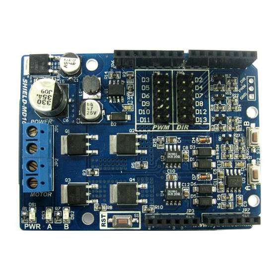
CCW depending on the connection). 5. Stackable Analog Input Header This is the analog port of the Arduino and is not used by SHIELD-MD10. The stackable header allows other stacked shield to utilize these pins. 6. Stackable Power Pins Header This is the power port of the Arduino. - Page 8 Motor Output B Connect to motor terminal B 12. PWM Pin Selector User may select D3, D5, D6, D9, D10 or D11 as the PWM pin for SHIELD-MD10 with the mini jumper. 13. DIR Pin Selector User may select D2, D4, D7, D8, D12 or D13 as the direction pin for SHIELD-MD10 with the mini jumper.
-
Page 9: Dimension
R OBOT . HEAD to TOE P roduct User’s Manual – S HIELD-MD10 5.0 DIMENSION Created by Cytron Technologies Sdn. Bhd. – All Right Reserved... -
Page 10: Hardware Installation
6.0 HARDWARE INSTALLATION This section shows the example of using SHIELD-MD10 with Arduino UNO as the main controller to control a brush motor. However, other Arduino main board such as Arduino Duemilanove and Arduino Mega can also be used. - Page 11 P roduct User’s Manual – S HIELD-MD10 Connect the brush motor and motor power to the terminal block on SHIELD-MD10 as shown. Don’t forget about the power source for the Arduino main board too. Power up the Arduino main board and load the sketch/program first before powering up the SHIELD-MD10 motor driver shield.
-
Page 12: Warranty
No. 16, Jalan Industri Ringan Permatang Tinggi 2, Kawasan Industri Ringan Permatang Tinggi, 14100 Simpang Ampat, Penang, Malaysia. Tel: +604-504 1878 Fax: +604-504 0138 URL: www.cytron.com.my Email: s upport@cytron.com.my sales@cytron.com.my Created by Cytron Technologies Sdn. Bhd. – All Right Reserved...
Need help?
Do you have a question about the SHIELD-MD10 and is the answer not in the manual?
Questions and answers