
Related Manuals for Chenbro RM43699


Summary of Contents for Chenbro RM43699
- Page 1 RM43699 Server Rackmount Server User Manual March 2020 Version 2.1 A document provides an overview of product features, functions, architecture, and support specifications...
- Page 2 No license (express or implied, by estoppel or otherwise) to any intellectual property rights is granted by this document. Chenbro disclaims all express and implied warranties, including without limitation, the implied warranties of merchantability, fitness for a particular purpose, and non-infringement, as well as any warranty arising from course of performance, course of dealing, or usage in trade.
-
Page 3: Table Of Contents
RM43699 Server Table of Contents Table of Contents ............................3 List of Figures ..............................4 List of Tables ..............................6 Product Overview .......................... 7 1-1 System Features Overview....................... 8 1-2 Front Panel ..........................9 1-3 Back Panel ..........................10 1-4 Front Control Panel ....................... 11 1-5 Chassis Dimensions ....................... -
Page 4: List Of Figures
RM43699 Server List of Figures Figure 1 Overview ............................ 8 Figure 2 Major components overview ...................... 8 Figure 3 Front panel ..........................9 Figure 4 Back panel overview ......................... 10 Figure 5 Front control panel ........................11 Figure 6 Chassis dimensions ........................12 Figure 7 Top cover removal ........................ - Page 5 RM43699 Server Figure 39 Slide rail installation - 1 (84H314610-003) ................33 Figure 40 Slide rail installation - 2 (84H314610-003) ................33 Figure 41 Slide rail installation - 3 (84H314610-003) ................34 Figure 42 2.5” OS drive carrier/3.5” drive carrier LED identification ............35 Figure 43 Backplane front view (front-right) .....................
-
Page 6: List Of Tables
RM43699 Server List of Tables Table 1 Chenbro RM43699 specifications ....................7 Table 2 Front control panel ........................11 Table 3 Slide rail options ........................13 Table 4 System environmental specifications summary ................14 Table 5 System packaging information ....................15 Table 6 Product weight information ....................... -
Page 7: Product Overview
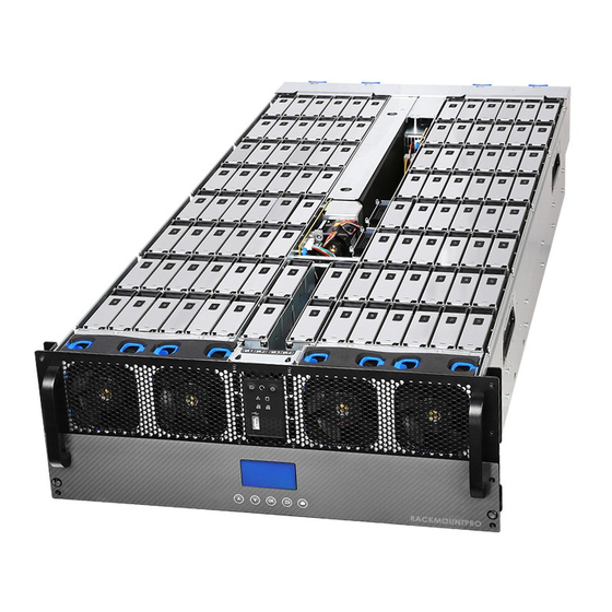
RM43699 Server 1. Product Overview RM43699, a 4U 100-bay ultra-density storage server chassis, supports dual-socket E5-2600 v4/v3 server motherboard, exclusive tool-less and hot-swap design, superior 1+1 CRPS 80 PLUS Platinum 2000W and thermal performance. This chapter provides a high-level overview of the system features and available options. More details for each major sub-system, feature, or option are provided in the following chapters. -
Page 8: System Features Overview
RM43699 Server 1-1 System Features Overview Figure 1 Overview Figure 2 Major components over view A. Top Cover Latch C. 3.5” Storage Drive Bay E. 2.5” Storage Drive Bay B. Front Hot-Swap Fan Module D. Middle Fixed Fan Module Product Overview... -
Page 9: Front Panel
RM43699 Server 1-2 Front Panel Figure 3 Front panel A. Rack Handles C. LCM Display B. Front Control Panel D. Front Hot-Swap Fan Module Product Overview │... -
Page 10: Back Panel
RM43699 Server 1-3 Back Panel Figure 4 Back panel overview A. Server Main Board Module C. Rear Hot-Swap Fan Module B. CRPS D. QIG Label Product Overview │... -
Page 11: Front Control Panel
RM43699 Server 1-4 Front Control Panel Figure 5 Front control panel Table 2 Front control panel Label ICON Indicator, button or connector UID Button/LED Reset Button/LED Power LED System Alarm LED LAN2 Activity LED HDD Activity LED LAN1 Activity LED USB2.0... -
Page 12: Chassis Dimensions
RM43699 Server 1-5 Chassis Dimensions Figure 6 Chassis dimensions Product Overview │... -
Page 13: Available Rack Mounting Kit Options (Refer To "Installation")
Advisory Note – Available rack and cabinet mounting kits are not designed to support shipment of the server system while installed in a rack. If you choose to do so, Chenbro advises you to verify your shipping configuration with appropriate shock and vibration testing before shipment. -
Page 14: System Level Environmental Specifications
RM43699 Server 1-7 System Level Environmental Specifications The following table defines the system level specifications under operating and non-operating environments. Table 4 System environmental specifications summary Parameter Specification Temperature Operating 5º C to 35º C (41º F to 95º F) -
Page 15: System Packaging
1-8 System Packaging The original Chenbro packaging, where the server system is delivered, is designed to provide protection for L6 configuration and tested to meet ISTA (International Safe Transit Association) Test Procedure 1A (2008). The packaging is also designed to be reused for shipment after the system integration has been completed. -
Page 16: System Components Removal And Installation
RM43699 Server 2. System Components Removal and Installation RM43699 supports for a variety of different storage options: 100 x 3.5” hot-swap SAS/SATA HDD 2 x 2.5’’ internal hot-swap SAS/SATA HDD or SSD [up to 9.5 mm thickness] Support for different storage and peripheral options will vary depending on the system model and/or available accessory options installed. -
Page 17: Top Cover Removal And Installation
RM43699 Server 2-1 Top Cover Removal and Installation Figure 7 Top cover removal 1. Loosen four screws on the cover. 2. Pull the latch as shown to release the cover. 3. Remove it by both hands. Figure 8 Top cover installation 1. -
Page 18: External Hot-Swap Hdd Assembly Removal And Installation
RM43699 Server 2-2 External Hot-Swap HDD Assembly Removal and Installation Figure 9 3.5” hot-swap HDD assembly removal 1. Open the lever to release the HDD assembly. 2. Pull the HDD assembly out of drive bay. Figure 10 3.5” hot-swap HDD assembly installation 1. -
Page 19: Figure 11 3.5" Hdd Removal (Tool-Less Type)
RM43699 Server Figure 11 3.5” HDD removal (tool-less type) 1. Bottom up the HDD assembly. 2. Press out the HDD by your two thumbs as shown. NOTE: Watch out the direction of HDD assembly while inserting. NOTE: Please operate it on a stable surface in case the HDD dropping unexpectedly. -
Page 20: Figure 13 2.5" Hot-Swap Hdd Assembly Removal (Tool-Less Type)
RM43699 Server Figure 13 2.5" hot-swap HDD assembly removal (tool-less type) 1. Press the carrier button, and release the lever. 2. Pull the HDD assembly out of drive bay. Figure 14 2.5’’ hot-Swap HDD assembly installation (tool-less type) 1. With the lever open, insert the HDD assembly into the drive bay until the bottom of chassis base. -
Page 21: Figure 15 2.5'' Hdd Removal (Tool-Less Type)
RM43699 Server Figure 15 2.5’’ HDD removal (tool-less type) 1. Bottom up the HDD assembly, and face the side without a concave slot of HDD carrier as shown. 2. Press out the HDD by your two thumbs as shown. NOTE: Please operate it on a stable surface in case the HDD dropping unexpectedly. -
Page 22: System Maintenance
RM43699 Server 2-3 System Maintenance Figure 17 Removal of whole system from the rack (tool-less type) 1. Loosen the thumb screws on both sides as shown. 2. Firmly hold the system by two persons at least, and pull the system out of cabinet. -
Page 23: Fan Module Removal And Installation
RM43699 Server 2-4 Fan Module Removal and Installation Figure 19 Front fan module removal - 1 (8038) Figure 20 Front fan module removal - 2 (8038) 1. Remove the shock-absorbing pads on the top of fan modules. 2. Grasp and press the finger grips of the fan module to release the module vertically as shown. -
Page 24: Figure 21 Front Fan Module Installation - 1 (8038)
RM43699 Server Figure 21 Front fan module installation - 1 (8038) Figure 22 Front fan module installation - 2 (8038) 1. Hold the finger grips of fan module as shown. NOTE: Ensure that the arrow sticker on the fan is toward the back of the chassis. -
Page 25: Figure 23 Rear Fan Module Removal (8038)
RM43699 Server Figure 23 Rear fan module removal (8038) 1 Press and hold the finger grips of rear fan module. 2. Disengage the module from the rear fan cage. Figure 24 Rear fan module installation (8038) 1. Hold the finger grips of rear fan module. -
Page 26: Server Main Board Removal And Installation
RM43699 Server 2-5 Server Main Board Removal and Installation Figure 25 Server main board docking board removal 1. Loosen three screws on the docking board as shown. 2. Remove the docking board vertically. Figure 26 Server main board removal 1. Loosen eight screws on the server main board as shown. -
Page 27: Figure 27 Server Main Board Installation
RM43699 Server Figure 27 Server main board installation 1. Place server main board into the MB tray. 2. Secure the server main board with eight screws. Figure 28 Server main board docking board installation 1. Install the docking board as shown. -
Page 28: Cpu/Dimm Installation And Removal
RM43699 Server 2-6 CPU/DIMM Installation and Removal Figure 29 Server main board CPU removal 1. Loosen four screws on the CPU Heatsink and remove it. 2. Release CPU socket latches. 3. Remove CPU cover and CPU from the socket. Figure 30 Server main board CPU installation 1. -
Page 29: Figure 31 Server Main Board Dimm Removal
RM43699 Server Figure 31 Server main board DIMM removal 1. Loosen two latches on the DIMM. 2. Remove DIMM from DIMM slot. Figure 32 Server main board DIMM installation 1. Install DIMM into DIMM slot. 2. Secure the DIMM with two latches. -
Page 30: Pcie Card Installation And Removal
RM43699 Server 2-7 PCIe Card Installation and Removal Figure 33 Server main board PCIe Card removal (right) 1. Loosen four screws as shown. 2. Disengage the riser card from the PCIe slot, detach PCIe Card from the riser card, and install the PCIe blank. -
Page 31: Figure 35 Server Main Board Pcie Card Removal (Left)
RM43699 Server Figure 35 Server main board PCIe Card removal (left) 1. Loosen three screws as shown. 2. Disengage the riser card from the PCIe slot, detach PCIe Card from the riser card, and install the PCIe blank. Figure 36 Server main board PCIe card installation (left) 1. -
Page 32: Psu Installation And Removal
RM43699 Server 2-8 PSU Installation and Removal Figure 37 CRPS removal 1. Press and hold CRPS latch while grasping the finger grip. 2. Pull CRPS out of the cage. installation Figure 38 CRPS 1. Press and hold CRPS latch while grasping the finger grip . -
Page 33: Slide Rail Installation
RM43699 Server 2-9 Slide Rail Installation Figure 39 Slide rail installation - 1 (84H314610-003) 1. Attach the inner rail to the chassis base while aligning T pins on the side of the system with the slots on the inner rail. -
Page 34: Figure 41 Slide Rail Installation - 3 (84H314610-003)
RM43699 Server Figure 41 Slide rail installation - 3 (84H314610-003) 4. Install the system into the rack by two persons at least due to the heavy weight. System Components Removal and Installation │... -
Page 35: Backplane
RM43699 Server 3. Backplane Each drive carrier includes separate LED indicators for drive activity and drive status. Light pipes integrated into the drive carrier assembly direct light emitted from LEDs mounted next to each drive connector on the backplane to the drive carrier faceplate, making them visible from the front of the system. -
Page 36: Storage Backplane Options
RM43699 Server 3-1 Storage Backplane Options RM43699 supports the below backplanes: 2 x 3.5” 26-port SAS/SATA active backplane (front) 2 x 3.5” 24-port SAS/SATA active backplane (rear) 1 x 2.5” 2-port SAS/SATA passive backplane (middle) All available SAS/SATA backplanes include the following common features: 12Gbps SAS and 6Gbps SAS/SATA ... -
Page 37: 26-Port 12Gbps Sata/Sas Active Backplane (Front-Right/Front-Left)
RM43699 Server 3-2 3.5” 26-Port 12Gbps SATA/SAS Active Backplane (Front-Right/Front-Left) Table 8 Backplane specifications Specification Host Interface Mini SAS HD HDD Interface SAS/SATA Hot-Swap Yes, allows users to replace devices online Display LED indicates storage devices status Error LED – Red (Error) -
Page 38: Figure 44 Backplane Front View (Front-Left)
RM43699 Server Figure 44 Backplane front view (front-left) . HDD_26 ~ HDD_31 . HDD_38 ~ HDD_43 . HDD_50 . HDD_32 ~ HDD_37 . HDD_44 ~ HDD_49 . HDD_51 Table 9 Connector and pin header function description Drawing Label Connector Description... -
Page 39: 24-Port 12Gbps Sata/Sas Active Backplane (Rear-Right/Rear-Left)
RM43699 Server 3-3 3.5” 24-Port 12Gbps SATA/SAS Active Backplane (Rear-Right/Rear-Left) Table 10 Backplane specifications Specification Host Interface Mini SAS HD HDD Interface SAS/SATA Hot-Swap Yes, allows users to replace storage devices online Display LED indicates storage device status Error LED – Red (Error) -
Page 40: Figure 46 Backplane Front View (Rear-Left)
RM43699 Server Figure 46 Backplane front view (rear-left) . HDD_76 ~ HDD_81 . HDD_88 ~ HDD_93 . HDD_82 ~ HDD_87 . HDD_94 ~ HDD_99 Table 11 Connector and pin header function description Drawing Label Connector Description Power The backplane includes two 3 * 2 Micro-Fit 3.0 mm connectors supplying power to the backplane. -
Page 41: Maintenance And Service
(Dead on Arrival) If the products are found Defect On Arrival, please contact Chenbro’s regional sales or CQE and indicate the defective status via email along with product photos and description. You may need to return the defective item by request.
Need help?
Do you have a question about the RM43699 and is the answer not in the manual?
Questions and answers