
Related Manuals for Chenbro RM146 Plus Series


Summary of Contents for Chenbro RM146 Plus Series
- Page 1 RM146 Plus Series Rackmount Chassis User Manual January 2020 Version 1.5 A document provides an overview of product features, functions, architecture, and support specifications.
- Page 2 No license (express or implied, by estoppel or otherwise) to any intellectual property rights is granted by this document. Chenbro disclaims all express and implied warranties, including without limitation, the implied warranties of merchantability, fitness for a particular purpose, and non-infringement, as well as any warranty arising from course of performance, course of dealing, or usage in trade.
-
Page 3: Table Of Contents
RM146 Plus Series Table of Contents List of Figures ..............................4 List of Tables ..............................6 Product Overview .......................... 7 System Features Overview ....................8 Front Panel ........................10 Back Panel ........................11 Front Control Panel ......................12 Chassis Dimensions ......................13 Available Rack Mounting Kit Options (Refer to “Installation”) .......... -
Page 4: List Of Figures
RM146 Plus Series List of Figures Figure 1 RM14604 Plus overview ......................8 Figure 2 RM14610 Plus overview ......................8 Figure 3 RM14604 Plus major components overview ................9 Figure 4 RM14610 Plus major components overview ................9 Figure 5 RM14604 Plus front panel ...................... - Page 5 RM146 Plus Series Figure 39 PCIe card blank removal ......................33 Figure 40 Cards and brackets installation ....................33 Figure 41 Single 1U PSU installation-1 ...................... 34 Figure 42 Single 1U PSU installation-2 ...................... 34 Figure 43 Redundant PSU module installation..................35 Figure 44 Redundant PSU module removal ....................
-
Page 6: List Of Tables
RM146 Plus Series List of Tables Table 1 Chenbro RM146 Plus series specifications..................7 Table 2 RM146 Plus series front control panel ..................12 Table 3 Slide rail options ........................14 Table 4 System environmental specifications summary ................15 Table 5 System packing information ....................... -
Page 7: Product Overview
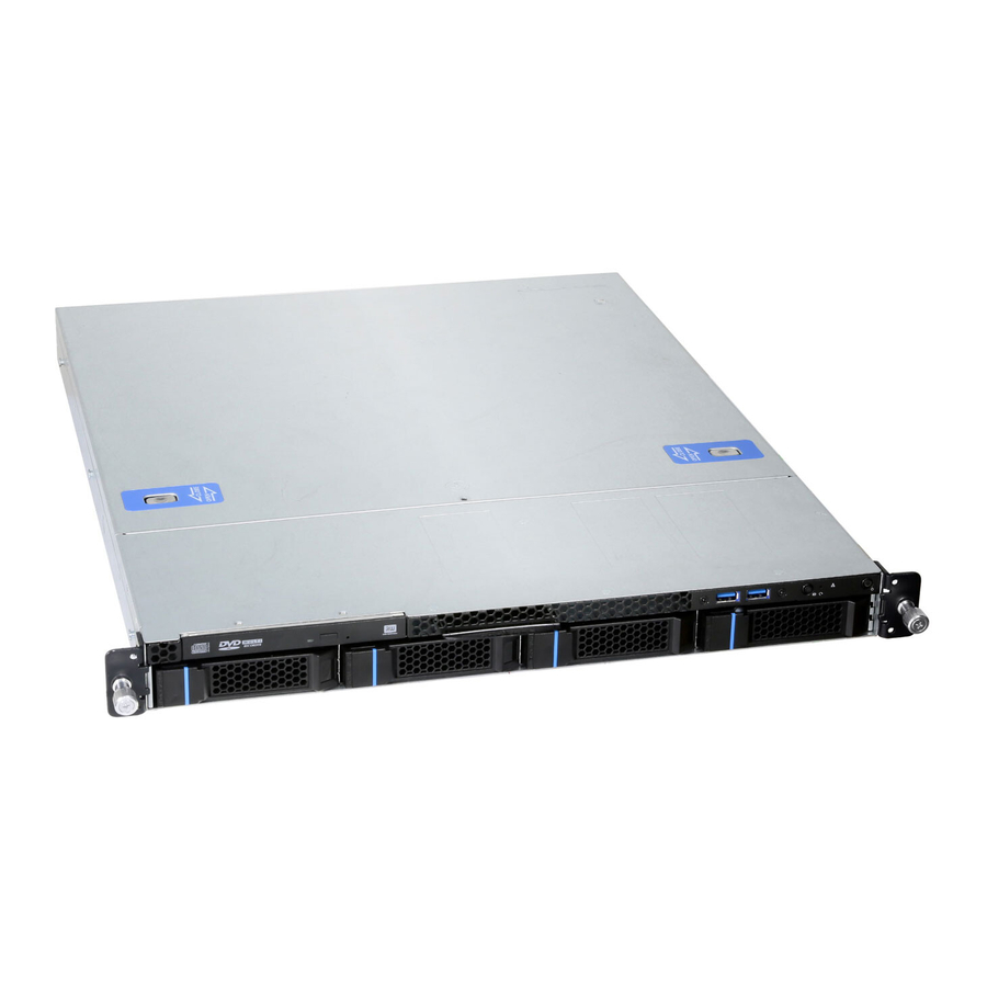
1. Product Overview RM146 Plus series is 1U cost effective server chassis, which supports up to ATX motherboard and delivers flexible configurations for specific applications. This chapter provides a high-level overview of the system features and available options. More details for each major sub-system, feature, or options are provided in the following chapters. -
Page 8: System Features Overview
RM146 Plus Series System Features Overview Figure 1 RM14604 Plus overview Figure 2 RM14610 Plus overview │... -
Page 9: Figure 3 Rm14604 Plus Major Components Overview
RM146 Plus Series Figure 3 RM14604 Plus major components over view Figure 4 RM14610 Plus major components over view A. Front Top Cover D. Rear Top Cover Latch G. Fan Assembly B. Back Top Cover E. Optical Drive Bay H. Server Board C. -
Page 10: Front Panel
RM146 Plus Series Front Panel Figure 5 RM14604 Plus front panel Figure 6 RM14610 Plus front panel A. Rack Handles C. Optical Drive Bay E. Front Control Panel B. Storage Drive Bay D. Info Tag F. Storage Sticker │... -
Page 11: Back Panel
RM146 Plus Series Back Panel Figure 7 Back panel with redundant PSU Figure 8 Back panel with single PSU A. 1U Redundant Power Supply C. I/O Gasket B. Single 1U Power Supply D. Full Height Expansion Slot │... -
Page 12: Front Control Panel
RM146 Plus Series Front Control Panel Figure 9 RM14604 Plus front control panel Figure 10 RM14610 Plus front control panel Table 2 RM146 Plus series front control panel Label ICON Indicator, button or connector Power Button LAN1, LAN2 Activity LED... -
Page 13: Chassis Dimensions
RM146 Plus Series Chassis Dimensions Figure 11 Chassis dimensions Figure 12 Embossed label dimensions │... -
Page 14: Available Rack Mounting Kit Options (Refer To "Installation")
Advisory Note – Available rack and cabinet mounting kits are not designed to support shipment of the server system while installed in a rack. If you choose to do so, Chenbro advises you verify your shipping configuration with appropriate shock and vibration testing before shipment. -
Page 15: System Level Environmental Specifications
RM146 Plus Series System Level Environmental Specifications The following table defines the system level specifications under operating and non-operating environments. Table 4 System environmental specifications summary Parameter Specification Temperature Operating 5º C to 35º C (41º F to 95º F) -
Page 16: System Packaging
System Packaging The original Chenbro packaging, where the server system is delivered, is designed to provide protection for L3 configuration and tested to meet ISTA (International Safe Transit Association) Test Procedure 1A (2008). The packaging is also designed to be reused for shipment after system integration has been completed. -
Page 17: System Components Installation
RM146 Plus Series 2. System Components Installation RM14604/RM14610 Plus support for a variety of different storage options: Up to 4 x 3.5” hot swap SAS/SATA HDD (RM14604 Plus) Up to 10 x 2.5” hot swap SAS/SATA HDD or SSD (RM14610 Plus) ... -
Page 18: Top Cover Installation
RM146 Plus Series Top Cover Installation Figure 13 Front top cover installation 1. Align the guide pins of this cover with the grooves on the chassis base, and slide the cover in (two guide pins for both sides). NOTE: Ensure that arrows on the cover indicating the back of the chassis. -
Page 19: Hdd Cage Installation
RM146 Plus Series HDD Cage Installation Figure 15 RM14604 Plus HDD cage installation 1. Align the grooves on the HDD cage with the guide pins of the chassis base, and slide the cage toward the back of the chassis. 2. Secure it with two screws as shown. -
Page 20: Hot-Swap Hdd Assembly Removal And Installation
RM146 Plus Series Hot-swap HDD Assembly Removal and Installation Figure 17 3.5” hot-swap HDD assembly installation 1. With the open lever, insert the HDD assembly into the drive bay until the end of the HDD cage. 2. Push in the lever when it is secured with a click. -
Page 21: Figure 19 3.5" Hdd Installation (Tool-Less Type)
RM146 Plus Series Figure 19 3.5” HDD installation (tool-less type) 1. Slide in the HDD until align the anchor point of HDD tray. 2. Push down the HDD when it is secured with a click. Figure 20 3.5” HDD installation (screw type) 1. -
Page 22: Figure 21 2.5" Hdd/Ssd Installation In 3.5" Tray (Screw Type)
1. Align the front of the HDD/SSD with the anchor point on the tray. 2. Secure the 2.5” HDD/SSD into the tray by three screws from the bottom as shown. NOTE: Dedicated screw type is required for 2.5” HDD/SSD Installation, Chenbro P/N: 384-14602-3143A0. │... -
Page 23: Figure 22 2.5'' Hot-Swap Hdd/Ssd Assembly Installation
RM146 Plus Series Figure 22 2.5’’ hot-swap HDD/SSD assembly installation 1. With the open latch, insert the HDD/SSD assembly into the drive bay until the end of the HDD/SSD cage. 2. Push in the lever when it is secured with a click. -
Page 24: Figure 24 2.5'' Hdd/Ssd Installation (Tool-Less Type)
RM146 Plus Series Figure 24 2.5’’ HDD/SSD installation (tool-less type) 1. Slide in the HDD/SSD until align the anchor points of HDD tray. 2. Push down the HDD/SSD when it is secured with a click. Figure 25 2.5” HDD/SSD installation (screw type) 1. -
Page 25: Internal 2.5'' Hdd Installation (Rm14604 Plus
RM146 Plus Series Internal 2.5’’ HDD Installation (RM14604 Plus) Figure 26 RM14604 Plus internal 2.5'' HDD installation 1. Attach the plastic bracket with HDD/SSD by engaging four pins with the dimples on one side of HDD/SSD. 2. Align the two dimples of the other side of HDD/SSD with the two hooks on the HDD/SSD cage as shown. -
Page 26: Internal Slim Odd Installation (Rm14604 Plus
RM146 Plus Series Internal Slim ODD Installation (RM14604 Plus) Figure 27 Slim ODD installation (RM14604 Plus) 1. Align two dimples on the ODD with two hooks on the cage, and slide the ODD in as shown. 2. Push the ODD down until it is secured with a click. -
Page 27: Internal 2.5" Hdd/Ssd Installation (Rm14610 Plus
RM146 Plus Series Internal 2.5” HDD/SSD Installation (RM14610 Plus) Figure 28 Internal 2.5’’ HDD/SSD bracket assembly (RM14610 Plus) 1. Place the HDD/SSD bracket in position as shown. 2. Secure the HDD/SSD bracket with three screws as shown. Figure 29 Internal 2.5” HDD/SSD Installation (RM14610 Plus) 1. -
Page 28: System Maintenance
RM146 Plus Series System Maintenance Figure 30 Installation of whole system into the rack (screw type) 1. Firmly grab the rack handles on both sides, and push the system all the way into the cabinet. 2. Secure the system with two thumb screws on both sides as shown. -
Page 29: Fan Assembly Installation
RM146 Plus Series Fan Assembly Installation Figure 32 Fan assembly installation (4028) 1. Attach the fan guard with fan as shown and secure it with two screws. 2. Insert four rivets with the fan as shown. Figure 33 Fan module installation (4028) 1. -
Page 30: Figure 34 Fan Assembly Installation (4048)
RM146 Plus Series Figure 34 Fan assembly installation (4048) 1. Attach the fan guard with fan as shown and secure it with two screws. 2. Attach the plastic extension holder with fan. 3. Insert four rivets with the fan as shown. -
Page 31: Figure 36 Fan Assembly Installation (4056)
RM146 Plus Series Figure 36 Fan assembly installation (4056) 1. Attach the fan guard with fan as shown and secure it with two screws. 2. Attach the plastic extension holder with fan. 3. Insert four rivets with the fan as shown. -
Page 32: Figure 38 Air Baffle Installation
RM146 Plus Series Figure 38 Air baffle installation 1. Insert the air baffle into the securing slot until it is locked. │... -
Page 33: Pcie Card Installation
RM146 Plus Series PCIe Card Installation Figure 39 PCIe card blank removal Remove the PCIe blank as shown. Figure 40 Cards and brackets installation Secure the riser card with PCIe bracket by two screws. Align two screw holes of PCIe slot bracket with the PCIe card as shown, and secure them with two screws. -
Page 34: Psu Installation
RM146 Plus Series 2-10 PSU Installation PSU installation-1 Figure 41 Single 1U PSU installation-2 Figure 42 Single 1U 1. Attach the PSU front bracket to the PSU cage, and secure it with two screws. 2. Secure the PSU front bracket to the chassis base with two screws as shown. -
Page 35: Figure 43 Redundant Psu Module Installation
RM146 Plus Series Redundant PSU module installation Figure 43 1. Insert the PSU module into the PSU cage and push until it is secured with a click. Redundant PSU module removal Figure 44 1. Press and hold the latch as shown. -
Page 36: Slide Rail Installation
RM146 Plus Series 2-11 Slide Rail Installation Figure 45 Slide rail installation-1 (84H314610-003) 1. Attach the inner rail to the chassis base while aligning T pins on the side of the system with the slots on the inner rail. Figure 46 Slide rail installation-2 (84H314610-003) 2. -
Page 37: Figure 47 Slide Rail Installation-3 (84H314610-003)
RM146 Plus Series Figure 47 Slide rail Installation-3 (84H314610-003) 3. Lift the latch as shown. 4. Secure the inner rail with one screw. Figure 48 Slide rail Installation-4 (84H314610-003) 5. Install the system into the rack with two hands. │... -
Page 38: Backplane
RM146 Plus Series 3. Backplane Each drive tray includes two LED indicators for drive activity and drive status. Operators can observe the system status from the front panel, as light pipes integrated into the drive tray directly light emitted from LEDs which are mounted on the backplane to the drive tray faceplate. -
Page 39: Storage Backplane Options
RM146 Plus Series Storage Backplane Options RM146 Plus series supports below backplanes: 4 x 3.5” SATA 7-pin port to port passive backplane 4 x 3.5” Mini-SAS HD passive backplane 10 x 2.5” Mini-SAS HD passive backplane All available SAS/SATA backplanes include the following common features: 12Gbps SAS, 6Gbps SAS/SATA ... -
Page 40: 3.5" 4-Port 12Gbps Port To Port Backplane
RM146 Plus Series 3.5” 4-port 12Gbps Port to Port Backplane Table 8 Backplane specifications Specification Host Interface SATA 7-pin HDD Interface SAS/SATA Hot Swap Yes, allows users to replace devices online Display LED indicates storage device status Power LED – Off (Fault) –... -
Page 41: Figure 51 Backplane Rear View
RM146 Plus Series Figure 51 Backplane rear view Table 9 Connector and pin header function description Drawing Label Description Description Power The backplane includes two 1 x 4 connectors supplying power to the backplane. Power is routed to the backplane via a power cable harness from the power supply. -
Page 42: 4-Port 12Gbps Mini-Sas Hd Passive Backplane
RM146 Plus Series 3.5” 4-port 12Gbps Mini-SAS HD Passive Backplane Table 10 Backplane specifications Specification Host Interface Mini -SAS HD HDD Interface SAS/SATA Hot Swap Yes, allows users to replace storage devices online Display LED indicates storage device status Power LED – Off (Fault) –... -
Page 43: Figure 53 Backplane Rear View
RM146 Plus Series Figure 53 Backplane rear view Table 11 Connector and pin header function description Drawing Label Description Description Power The backplane includes one 2 x 2 connector supplying power to the backplane. Power is routed to the backplane via a power cable harness from the power supply. -
Page 44: 2.5" 10-Port 12Gbps Mini-Sas Hd Passive Backplane
RM146 Plus Series 2.5” 10-port 12Gbps Mini-SAS HD Passive Backplane Table 12 Backplane specifications Specification Host Interface Mini SAS HD HDD Interface SAS/SATA Hot Swap Yes, allows replace devices online Display LED indicates storage device status Power LED – Off (Fault) –... -
Page 45: Figure 55 Backplane Rear View
RM146 Plus Series Figure 55 Backplane rear view Table 13 Connector and pin header function description Drawing Label Description Description Power The backplane includes one 2 x 2 connector supplying power to the backplane. Power is routed to the backplane via a power cable harness from the power supply. -
Page 46: Maintenance And Service
(Dead on Arrival) If the products are found Defect On Arrival, please contact Chenbro’s regional sales or CQE and indicate the defective status via email along with product photos and description. You may need to return the defective item by request.
Need help?
Do you have a question about the RM146 Plus Series and is the answer not in the manual?
Questions and answers