Table of Contents
Advertisement
Quick Links
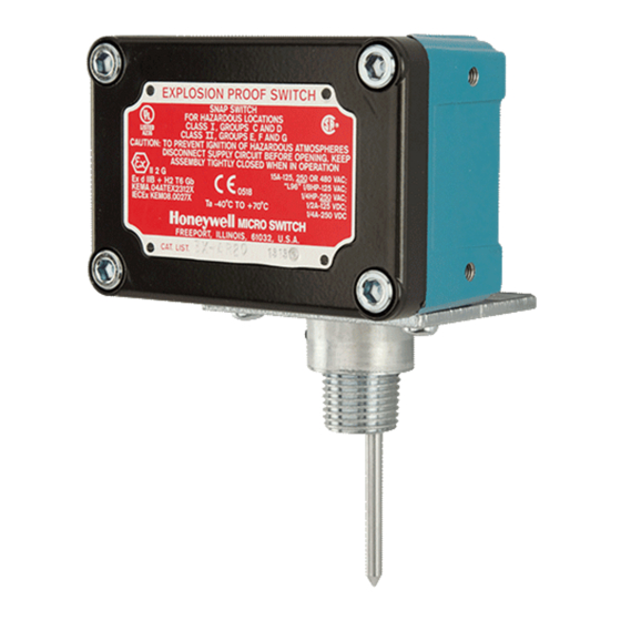
INSTALLATION AND MAINTENANCE INSTRUCTIONS
PIBVEXP Explosion Proof
Post Indicator and Butterfly Valve Switch
Specifications
Contact Ratings:
Dimensions:
Operating Temperature Range:
Maximum Stem Extension:
Shipping Weight:
Enclosure Rating:
Important
Please Read Carefully and Save
This instruction manual contains important information on
the installation and operation of supervisory switches.
Purchasers who install supervisory switches for use by oth-
ers must leave this manual or a copy of it with the user.
These instructions apply to System Sensor switches for post
indicator and butterfly type valves. Read all instructions
carefully before beginning. Follow only those instructions
that apply to the model being installed.
To prevent ignition of hazardous atmospheres, disconnect
supply circuit before opening. Keep assembly tightly closed
when in operation. Do NOT leave unused wires exposed.
All supervisory switch installations must comply with local
codes and ordinances and the requirements of the authority
having jurisdiction. Additional information is available in
National Fire Protection Association standards NFPA 13,
13D, 13R, 71, and 72.
D770-28-00
Technical Manuals Online! - http://www.tech-man.com
One SPDT (Form C) Switch
15 A @ 125/250/480 VAC; 1/8 HP @ 125 VAC, 1/4 HP @ 250 VAC
1/2 A @ 125 VDC; 1/4 A @ 250 VDC
3.75"L X 3.25"D X 4.5"H
-40° F - 160° F (-40° C – 71° C)
2.1875"
1-3/4 lb.
UL Listed explosion proof switch enclosure for use in hazardous locations.
Class I, Groups C and D; Class II, Groups E. F and G
CAUTION
3825 Ohio Avenue, St. Charles, Illinois 60174
General Information for Post Indicator Valves and
Butterfly Valves
1. Model PIBVEXP is designed for installation in a
tapped hole and located so that the actuating lever of the
switch engages the target or flag of the valve . The switch
actuating lever is spring loaded against the flag or target of
the valve and is released when the valve moves toward
the closed position from the fully open position.
2. Model PIBVEXP is equipped with a removable
pipe nipple which is locked in place with two set screws.
A hex wrench is provided for this feature. These models
also include an adjustable length actuating lever which
eliminates any need for alteration of the length of the lever.
1
A Division of Pittway
1-800-SENSOR2, FAX: 630-377-6495
1
/
" NPT
2
1
/
" NPT
2
I56-1430-000
Advertisement
Table of Contents

Related Manuals for Pittway System Sensor PIBVEXP


Summary of Contents for Pittway System Sensor PIBVEXP
- Page 1 INSTALLATION AND MAINTENANCE INSTRUCTIONS PIBVEXP Explosion Proof A Division of Pittway 3825 Ohio Avenue, St. Charles, Illinois 60174 Post Indicator and Butterfly Valve Switch 1-800-SENSOR2, FAX: 630-377-6495 Specifications Contact Ratings: One SPDT (Form C) Switch 15 A @ 125/250/480 VAC; 1/8 HP @ 125 VAC, 1/4 HP @ 250 VAC 1/2 A @ 125 VDC;...
- Page 2 Figures 1A and 1B: 5. Replace the head and target assembly. 6. Screw the locknut onto the threaded nipple which is Falling flag Rising Flag supplied with the PIBVEXP. 7. Screw the nipple hand tight into the " hole in the valve and tighten the locknut against the housing to se- cure the nipple in position.
- Page 3 the unit must be oriented so the flag falls away from the Figure 2: actuating lever when the valve is closed. Apply pressure to PIBVEXP and tighten set screws to secure the assembly. 7. Slide the actuating arm into the valve until it bottoms on the flag, but do not tighten the lever screw.
- Page 4 WARNING The Limitations of Supervisory Switch Alarm Devices Alarms generated by the activation of the actuating lever Supervisory switches are not a substitute for insurance. may not be received by a central station if telephone or Building owners should always insure property and lives other communication lines to the alarm device are out of being protected.
Need help?
Do you have a question about the System Sensor PIBVEXP and is the answer not in the manual?
Questions and answers