Advertisement
INSTALLATION AND MAINTENANCE INSTRUCTIONS
EPS10EXP Explosion Proof
Alarm Pressure Switch
Specifications
Contact Ratings:
Operating Temperature Range:
Maximum Service Pressure:
Maximum Adjustment Range:
Enclosure Rating:
Hazardous Atmospheres Classification: Class I, Groups B, C, D, Div. 1
Approximate Differential:
Important
Please Read Carefully and Save
This instruction manual contains important information
about the installation and operation of alarm pressure
switches. Purchasers who install switches for use by others
must leave this manual or a copy of it with the user.
Read all instructions carefully before installation, following
only those instructions that apply to the model you are in-
stalling.
Before installing any alarm device, be thoroughly familiar
with:
NFPA 72:
Installation, Maintenance, and Use of Protec-
tive Signaling Systems
NFPA 13:
Installation of Sprinkler Systems
Other applicable NFPA standards, local codes, and the re-
quirements of the authority having jurisdiction.
Failure to follow these directions may result in failure of the
device to report an alarm condition. System Sensor is not
responsible for devices that have been improperly installed,
tested, or maintained.
Operation
As pressure changes, a diaphragm actuates 2 snap action
switches. The pressure switch actuation is determined by
adjustment settings.
D770-25-00
Technical Manuals Online! - http://www.tech-man.com
10 A, 1/2 HP @ 125/250 VAC
2.5 A @ 6/12/24 VDC
–40° F to +160° F
250 PSI
4 – 20 PSI
NEMA Type 4 — Indoor or/Outdoor Use
Class II, Groups E, F, G, Div. 1
Class III, Div. 1
3 PSI throughout range
To prevent ignition of hazardous atmospheres, disconnect
circuits before removing cover. Keep cover closed while cir-
cuits are live. Conduit runs must have sealing fittings con-
nected within 18" of the enclosure.
Installation
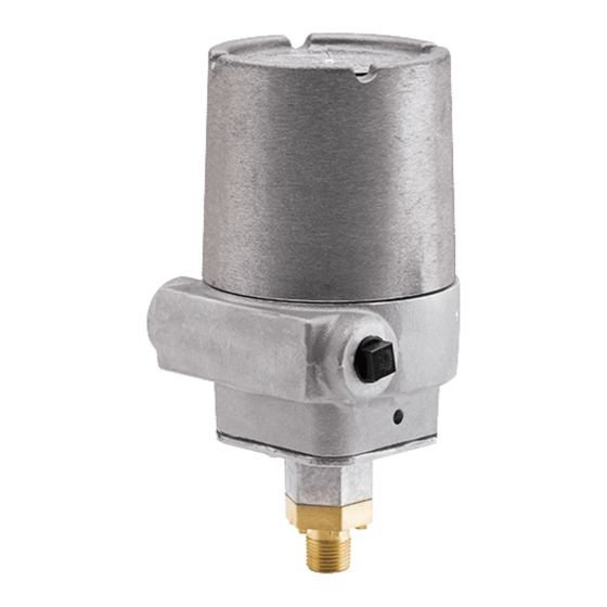
1. Back out cover tamper set screw and remove cover (Fig. 1).
2. Mounting the Switch
The device is designed to be mounted in the upright or
horizontal position; side mounting is also acceptable.
Figure 1. Pressure switch basic dimensions:
COVER
1
3825 Ohio Avenue, St. Charles, Illinois 60174
1-800-SENSOR2, FAX: 630-377-6495
WARNING
4.9"
LOCKING
SCREW
A Division of Pittway
HEX ADJUST
SCREW
1/4" HEX HEAD
COVER
TAMPER
SET SCREW
(WRENCH
PROVIDED)
ADJUSTMENT
WHEEL
9.5"
COVER
(WRENCH
PROVIDED)
MAIN ADJUSTMENT
WHEEL (TURN
COUNTERCLOSKWISE
TO INCREASE
PRESSURE)
1/2" NPT
I56-1427-000
Advertisement
Table of Contents

Related Manuals for Pittway System Sensor EPS10EXP


Summary of Contents for Pittway System Sensor EPS10EXP
- Page 1 INSTALLATION AND MAINTENANCE INSTRUCTIONS EPS10EXP Explosion Proof A Division of Pittway 3825 Ohio Avenue, St. Charles, Illinois 60174 Alarm Pressure Switch 1-800-SENSOR2, FAX: 630-377-6495 Specifications Contact Ratings: 10 A, 1/2 HP @ 125/250 VAC 2.5 A @ 6/12/24 VDC Operating Temperature Range: –40°...
- Page 2 Figure 2. Typical piping diagram for EPS10EXP WIRE TO ALARM WIRE TO ALARM WIRE TO ALARM INDICATING CIRCUIT INDICATING CIRCUIT INDICATING CIRCUIT EPS10EXP OF FIRE ALARM EPS10EXP OF FIRE ALARM EPS10EXP OF FIRE ALARM CONTROL PANEL CONTROL PANEL CONTROL PANEL WATER SPRINKLER SPRINKLER...
- Page 3 Adjustments To Factory Settings NOTE: The sensor assembly is not field replaceable. Do The EPS10EXP device is pre-adjusted at the factory to alarm not attempt to disassemble these parts. If you have at 4–8 PSI on rising pressure (see Table 2). Pressure switch any questions, consult System Sensor.
- Page 4 Three-Year Limited Warranty System Sensor warrants its enclosed pressure switch to be free from de- ment, RA #__________, 3825 Ohio Avenue, St. Charles, IL 60174. Please fects in materials and workmanship under normal use and service for a include a note describing the malfunction and suspected cause of failure. period of three years from date of manufacture.
Need help?
Do you have a question about the System Sensor EPS10EXP and is the answer not in the manual?
Questions and answers