Advertisement
Table of Contents
- 1 Important Please Read Carefully and Save
- 2 General Installation Considerations
- 3 Section 1 Installation Instructions for Post Indicator Valves
- 4 Section 2 Installation Instructions for Butterfly Valves
- 5 Section 3 General Installation Instructions
- 6 Section 4 Reversing the Action of PIBV2
- 7 Three-Year Limited Warranty
- 8 The Limitations of Supervisory Switch Alarm Devices
- Download this manual
INSTALLATION AND MAINTENANCE INSTRUCTIONS
PIBV2 Post Indicator and
Butterfly Valve Supervisory Switch
Specifications
Contact Ratings:
Dimensions:
Maximum Stem Extension:
Operating Temperature Range:
Shipping Weight
Enclosure Rating:
Important
Please Read Carefully and Save
This instruction manual contains important information on
the installation and operation of supervisory switches.
Purchasers who install supervisory switches for use by oth-
ers must leave this manual or a copy of it with the user.
These instructions apply to System Sensor switches for post
indicator and butterfly type valves. Read all instructions
carefully before beginning installation.
Do NOT use this switch in explosive or potentially
explosive atmospheres.
Do NOT leave unused wires exposed.
Before installing any supervisory switches in sprinkler sys-
tems, be thoroughly familiar with:
NFPA 72:
Installation, Maintenance and Use of Local
Protective Signalling Systems
NFPA 13:
Installation of Sprinkler Systems, specifi
cally, Section 3.17
NFPA 25:
Inspection, Testing and Maintenance of
Sprinkler Systems, specifically Chapters 4
and 5
General Installation Considerations
1. Model PIBV2 is designed for installation in a
tapped hole and located so that the actuating lever of the
switch engages the target or flag of the valve . The
switch actuating lever is spring loaded against the flag or
target of the valve and is released when the valve moves
toward the closed position from the fully open position.
The switch is factory set to indicate an alarm condition
when the target and lever move in the direction toward
the conduit entry hole when the valve closes, but can be
reversed if the installation demands (refer to Section 4).
2. Model PIBV2 is equipped with a removable
N770-03-00
Technical Manuals Online! - http://www.tech-man.com
10A @ 125/250 VAC
2.5 A @ 24 VDC
1
1
8
/
H X 3
/
W X 3
4
2
2
5
/
"
32
32° F - 120° F (0° C - 49° C)
2 lbs.
NEMA Type 3R when mounted with the actuator vertical (cover on top) as tested by
Underwriters Laboratories, Inc.
CAUTION
1
/
" NPT
2
1
/
" NPT
2
1
/
" D
4
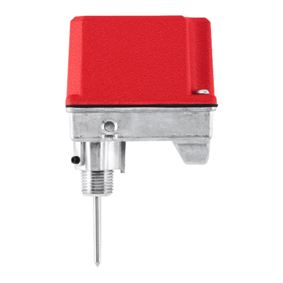
Figure 1:
Cover
Tamper screws
Tamper proof
wrench
(P/N WFDW)
Actuating cam
Actuating lever
set screw
Nipple set screws
Threaded nipple
3-1/4" D
Hex wrench
(P/N HEXW)
pipe nipple which is locked in place with two set screws.
These models also include an adjustable length actuat-
ing lever which eliminates any need for alteration of the
length of the lever. A hex key is furnished for both of
these features.
3. The cover is secured with two tamper resistant screws
which require a special key to remove. One key is in-
cluded with each supervisory switch. Replacement and
additional keys are available (Part No. WFDW).
1
A Division of Pittway
3825 Ohio Avenue, St. Charles, Illinois 60174
1-800-SENSOR2, FAX: 630-377-6495
4-1/4" H
(Assembled)
Spring
Mounting screws
Switch Enclosure
Base housing
3-1/2" W
Actuating lever
Retaining nut
A78-1587-00
I56-394-06
Advertisement
Table of Contents

Related Manuals for Pittway System Sensor PIBV2


Summary of Contents for Pittway System Sensor PIBV2
- Page 1 INSTALLATION AND MAINTENANCE INSTRUCTIONS PIBV2 Post Indicator and A Division of Pittway 3825 Ohio Avenue, St. Charles, Illinois 60174 Butterfly Valve Supervisory Switch 1-800-SENSOR2, FAX: 630-377-6495 Specifications Contact Ratings: 10A @ 125/250 VAC 2.5 A @ 24 VDC Dimensions: H X 3 W X 3 "...
- Page 2 Figures 2A and 2B: location. Drill with a " drill bit and tap a " NPT thread. Rising Flag Falling flag 5. Replace the head and target assembly. 6. Screw the locknut onto the threaded nipple which is supplied with the PIBV2. 7.
- Page 3 Figure 3: Actuator Vertical (Pointing Up) 2. Ground Screw — A ground screw is provided with all supervisory switch models. When grounding is required, clamp wire with the screw in hole located near conduit entrance. A78-1633-00 3. Wiring — See Figure 6, Page 4. nipple, orienting the PIBV2 to trip the switch as the Section 4 valve closes.
- Page 4 Figure 6: NOTE: Common and B connections will close when valve moves 1/5 of its total travel distance. Top View Switch 1 CONTACT RATINGS Switch 2 125/250 VAC 10 AMPS Strip Gauge 24 VDC 2.5 AMPS Sup. Switch Sup. Switch end-of-line resistor to nonsilenceable initiating zone of listed FACP...
Need help?
Do you have a question about the System Sensor PIBV2 and is the answer not in the manual?
Questions and answers