Advertisement
Available languages
Available languages
Quick Links
WARNING
In order to reduce the risk of personal injury and damage to equipment, basic safety precaution should always
be followed when assembling and using this product. Read all instructions carefully before assembly and use.
Some parts may contain sharp edges. Wear protective gloves if necessary.
In order to ensure safe assembly, it is recommended that this product be assembled by at least two
people.
Keep children and pets away from the assembly area.
Begin the assembly at least 6' (1.8 m) away from any obstruction, such as a fence, garage, house,
overhanging branches, laundry line, or electrical wires.
Install this gazebo on level ground. This gazebo cannot be permanently stacked or attached to a
concrete floor or platform. This gazebo is intended for decorative and sunshade purposes only, and is
not designed to withstand harsh weather, including high winds, rain, and snow.
Verify that all nuts and bolts are tightly secured before and during use.
Remove the canopy or take other precautions in high wind conditions.
Anchor or stake a minimum of four (4) locations of the unit to the ground for added safety and security.
Assembly Instructions
088-0383-0
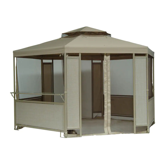
gardenview gazebo
1 of 6
Advertisement

Subscribe to Our Youtube Channel
Related Manuals for for Living 088-0383-0


Summary of Contents for for Living 088-0383-0
- Page 1 Assembly Instructions 088-0383-0 gardenview gazebo WARNING In order to reduce the risk of personal injury and damage to equipment, basic safety precaution should always be followed when assembling and using this product. Read all instructions carefully before assembly and use.
- Page 2 PostⅠ A1 1 PostⅡ A2 1 Post Ⅲ A3 2 Post Post Side Panel Frame Fixture Frame Fixture Frame Fixture Corner Connector Beam Slanting Bar Top Connector Hook Bar Table Board Large Canopy Small Canopy Mosquito Netting 2 of 6...
-
Page 3: Hardware Pack
Tools required: Hammer, Ladder, Screwdriver (not included) Hardware Pack 1 M5×15 Bolt 24 pcs M5 Flat Washer 24 pcs Step.1 Fig.2 Fig.1 Fig.2 A1/A2 /A3/B A1/A2/A3/B/C Fig.1 Fig.1: Connect Side Panel D to Post A1, A2, A3, B, C. Fig.2: Connect Connector H to Post A1, A2, A3, B, C, Beam I, and tighten them by using Bolt BB and Flat Washer CC. 3 of 6... - Page 4 Hardware Pack2 M6×30 Bolt 6 pcs M6Flat Washer 12 pcs M6 Nut 6 pcs M6 Wrench 1 pc Fig.3 Step.2 Fig.4 Fig.5 Fig.3 Fig.5 FF JJ Fig.4 Fig.3: Connect Slanting Bar J and Top Connector K by using Bolt EE, Flat Washer JJ, and Nut FF. Then screw Hook L into Top Connector K.
- Page 5 Hardware Pack3 M6×15 Bolt 2 pcs M5×15 Bolt 20 pcs Flat Washer 20 pcs Plastic Flat Washer 4 pcs M6×30 Bolt 2 pcs M6 Flat Washer 2 pcs 6×180 mm Stake 8 pcs Plastic Ring 50 pcs Step.3 Fig.6 Fig.9 Fig.8 Fig.7 5 of 6...
- Page 6 Fig.7 A2/A3/C Fig.6: Connect Bar Table Board M to Post B, C, and tighten them by using Bolts AA, EE and Flat Washer DD, JJ. Fig.7: Attach Frame Fixture F, G to Post A2, A3, C, Side Panel D and tighten them by using Bolt BB and Flat Washer CC, then secure it by using Stake HH.
-
Page 7: Instructions De Montage
Instructions de montage 088-0383-0 Abri de jardin panorama AVERTISSEMENT Afin d'éviter le risque de blessures et de dommage matériel, des mesures de sécurité élémentaires doivent être prises lors du montage et de l'utilisation de cet article. Lisez toutes les instructions attentivement avant le montage et l’utilisation. - Page 8 Poteau I A1 1 Poteau II A2 1 Poteau III A3 2 Poteau Poteau Panneau latéral Fixation de charpente E Fixation de charpente F Fixation de charpente G Raccord angulaire Poutre Barre oblique Raccord de toit Crochet Table de bar Grande toile Petite toile Moustiquaire...
- Page 9 Outils requis : marteau, échelle, tournevis (non inclus) ensemble de fixations Boulon M5 × 15 24 pièces Rondelle plate M5 24 pièces étape Fig.2 Fig.1 Fig.2 A1/A2 /A3/B A1/A2/A3/B/C Fig.1 Fig. 1 : Fixez les panneaux latéraux D aux poteaux A1, A2, A3, B, C. Fig.
- Page 10 ensemble de fixations Boulon M6 × 30 6 pièces Rondelle plate M6 12 pièces Écrou M6 6 pièces Clé M6 1 pièce Fig.3 étape Fig.4 Fig.5 Fig.3 Fig.5 FF JJ Fig.4 Fig. 3 : Fixez les barres obliques J au raccord de toit K à l'aide des boulons EE, des rondelles plates JJ et des écrous FF.
- Page 11 ensemble de fixations Boulon M6 × 15 2 pièces Boulon M5 × 15 20 pièces Rondelle plate 20 pièces Rondelle plate en plastique 4 pièces Boulon M6 × 30 2 pièces Rondelle plate M6 2 pièces Piquet de 6 × 180 mm 8 pièces Anneau en plastique 50 pièces...
- Page 12 Fig.7 A2/A3/C Fig. 6 : Placez la table de bar M contre les poteaux B et C et fixez-la à l'aide des boulons AA, EE et des rondelles plates DD, JJ. Fig. 7 : Placez les fixations de charpente F et G contre les poteaux A2, A3, C et les panneaux latéraux D, puis fixez-les à...
Need help?
Do you have a question about the 088-0383-0 and is the answer not in the manual?
Questions and answers