Table of Contents
Advertisement
Quick Links
CE Use and Maintenance Manual
Bike-Lift EUROPE s.r.l.
via Don Milani, 40/42
43012 Sanguinaro di Fontanellato (PARMA)
Website:
www.bikelifteurope.it
E-mail:
info@bikelifteurope.it
Operating Manual no. 057-2-6-0016-R0
Version 2021
Scissor lifting platform
CUSTOM 500
Model
CU500-003
Version
ELECTRO-HYDRAULIC PUMP
–
Italy
EN
P. 1
Advertisement
Table of Contents

Related Manuals for Bike-Lift CUSTOM 500


Summary of Contents for Bike-Lift CUSTOM 500
- Page 1 CE Use and Maintenance Manual Scissor lifting platform CUSTOM 500 Model Version CU500-003 ELECTRO-HYDRAULIC PUMP Bike-Lift EUROPE s.r.l. via Don Milani, 40/42 – 43012 Sanguinaro di Fontanellato (PARMA) Italy Website: www.bikelifteurope.it E-mail: info@bikelifteurope.it Operating Manual no. 057-2-6-0016-R0 P. 1...
-
Page 2: Table Of Contents
2.3 Machine description ......................... 11 2.4 Intended use ............................. 12 2.5 Technical specifications ........................13 2.5.1 CUSTOM 500 ..........................13 Safety section ..........................14 3.1 Environmental working values ......................14 3.2 Sound level ............................14 3.3 Residual risks ............................ 14 3.4 Operator protections ........................ - Page 3 Commissioning ..........................21 Dismantling/scrapping section ......................22 Dismantling ............................22 Mechanical dismantling ........................22 Scrapping ............................22 Operation section ..........................23 Loading operations .......................... 23 Unloading operations ........................23 Lifting types ............................. 24 7.3.1 Electro-hydraulic pump – term code -003 ................24 Maintenance section........................
-
Page 4: Information Section
Information section 1.1 Preface The EC Use and Maintenance Manual is a document issued by Bike-Lift Europe s.r.l. as an integral part of the Machine. The purpose of this publication is to provide the operator with efficient and safe instructions regarding the use and maintenance operations. -
Page 5: Prohibitions
It also becomes void if the product has been submitted to performances exceeding those indicated by Bike-Lift - Europe s.r.l. 1.3.2 Insurance All Bike-Lift s.r.l products are insured with an RCP policy with a price ceiling of € 3.000.000. Damages caused by negligence or tampering are excluded. Operating Manual no. 057-2-6-0016-R0 P. -
Page 6: Manufacturer Identification
1.4 Manufacturer identification Bike-Lift EUROPE s.r.l. via Don Milani, 40/42, 43012 Sanguinaro di Fontanellato (PARMA) – Italy Web site: www.bikelifteurope.it E-mail: info@bikelifteurope.it Tel: 0039-0521-827091 Fax: 0039-0521-827064 1.5 Technical assistance and spare parts To order spare parts, it is recommended to specify exactly the following data: Model and serial number of the machine;... -
Page 7: Ce Declaration Of Conformity
Company: Bike-Lift EUROPE S.r.l. Address: Via Don Milani, 40/42 - 43012 Sanguinaro di Fontanellato (PR) - Italy Declares under its sole responsibility that the machine: Designation: CUSTOM 500 Lifting platform Model: CU500-003 Serial number: Year: Function: Lifting of motorcycles for vehicle maintenance operations Complies with the essential safety requirements of the following Directives: ... -
Page 8: Normative References
1.7 Normative references The machine is identified by the CE marking drawn up according to the specifications of the Machinery Directive 2006/42/EC and subsequent amendments. Reference Title 2006/42/EC Machinery Safety Directive 2014/30/EC Electromagnetic Compatibility Directive (EMC) 2014/35/EU Low Voltage Directive (LVD) Safety of machinery - General principles of design - Risk UNI EN ISO 12100:2010 assessment and risk reduction. -
Page 9: Key
1.8 Key LIFT: electro-hydraulic scissor handling system for the maintenance and repair of motorcycles and scooters. The specific identification of the lift is indicated on the cover. OPERATOR: In compliance with Directive 2006/42/EC and subsequent amendments, it is specified that the term "operator" means the person(s) in charge of installing, operating, adjusting and cleaning the lift. -
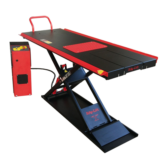
Page 10: Machine Description
Machine description 2.1 Machine name Scissor lifting platform for the maintenance and repair of motorcycles and scooters with a maximum capacity of 500 kg. The movement of this Bike - Lift lifting platform takes place by means of an electro-hydraulic system. -
Page 11: Machine Description
2.3 Machine description The machine known as lifting platform is a suitable equipment to support motorcycles and scooters during the maintenance and repair phases in a comfortable and safe way. The basic parts of the lifting platform (Figure 2) are: Figure 2 –... -
Page 12: Intended Use
2.4 Intended use Disseminate the instructions described in this chapter to all personnel involved in the preparation and use of the machine. The machine is intended for lifting motorcycles and scooters for maintenance purposes. The machine has been designed and built for the specified use; a different use and non- compliance with the technical parameters set by the Manufacturer may be dangerous for the operators. -
Page 13: Technical Specifications
2.5 Technical specifications 2.5.1 CUSTOM 500 (see exploded diagram attached to this manual) CUSTOM 500 VERTICAL SCISSOR LIFTING PLATFORM PARAMETER VALUE Maximum bearing 500 kg Maximum height 110 cm Minimum height 9 cm Length 220 cm Lifting surface size 220 x 80 cm Mobile ascent ramp size 51.6 x 24 cm... -
Page 14: Safety Section
Safety section 3.1 Environmental working values The use environment of the machine must be well lit, must not present explosion hazards of any kind and must be protected from atmospheric precipitation. The machine works properly within the following values: Ambient temperature between 5° and 40° C; ... -
Page 15: Operator Protections
The putting out of service of the protection and safety devices for protecting the operators is the sole responsibility of the Purchaser or the Machine's user. Finally, we remind you that the handling, installation, use, maintenance and decommissioning of the machine represent a source of hazard if these operations are not performed in compliance with the requirements of this Manual or without the necessary caution and attention required. -
Page 16: Pictograms
During the use of the lift it is very important to pay the utmost attention to the ascent and descent maneuvers. During the ascent/descent phase the operator is required to distance from the lift according to the length allowed by the control panel cable. The personnel who are not in charge of using the lift must not pass or stand in the operating area of the motorcycle lifting platform. -
Page 17: Transport And Handling
Transport and handling section 4.1 Transport, handling and storage WARNING: Disseminate the instructions described in this chapter to all personnel involved in the transport and handling of the machine. For safety reasons, the moving parts must be locked before transport. 4.2 Packaging and transport The machine is packed for transport directly from the Manufacturer. -
Page 18: Receipt And Check
This Operator must pay maximum attention to all transport phases. Do not allow any other person to stand in the operating area of the forklift truck in order to prevent the accidental fall of the boxes. During the unloading phase, in any case, pay attention to the vehicles and people in transit. Make sure there are not many holes in the floor or on the high slope ramps for the vehicle used, in relation to the load carried;... -
Page 19: Installation Section
Installation section The machine must be installed in compliance with the safety regulations and instructions included in this chapter. WARNING: COMPLETELY remove the wooden sleepers located under the lifting platform by removing the fixing screws before using the machine. The machine does not need a base, but requires a flat and horizontal floor. The floor must be able to support a minimum weight of 1000 kg/m2. -
Page 20: Ascent Ramp Assembly
5.1 Ascent ramp assembly Hook the ascent ramp to the leg of the lift (Figure 5, [1]) when the work surface is at a height less than 40 cm from the ground. During the ascent the ramp is blocked and will consequently move toward the lift. -
Page 21: Commissioning
5.3 Commissioning The tests to be carried out before using the machine have the task of verifying that the mechanical and electrical installation (in the electro-hydraulic pump versions) has been carried out correctly and there are no breakages or damages that could compromise the proper functioning and the performance of the machine. -
Page 22: Dismantling/Scrapping Section
Dismantling/scrapping section 6.1 Dismantlement Follow the materials dismantling Regulations in force in the country where the machine will be dismantled. Here are some useful indications in case you must disassemble the machine to reassemble it in other areas, store it or dismantle it. 6.2 Mechanical dismantling Before proceeding with mechanical dismantling of the machine, carefully clean the whole structure (see Cleaning and Maintenance chapter). -
Page 23: Operation Section
Operation section – Figure 6 Lift components 7.1 Loading operations Before installing the vehicle on the platform it is essential to use the wheel lock (Figure 6, [1]), to check that the work surface (Figure 6, [2]) is completely lowered and the ascent ramp (Figure 6, [3]) is properly positioned. -
Page 24: Lifting Types
It is absolutely forbidden to lift motorcycles while leaning on the side kickstand. Do not try to lift motor vehicles weighing more than the maximum capacity of the platform. Do not stand under the vehicle during maintenance phases. 7.3 Lifting types 7.3.1 Electro-Hydraulic pump –... -
Page 25: Maintenance Section
Maintenance section The maintenance operation is the absolute prerogative of professional operators and specialized technicians, in compliance with the requirements of Machinery Directive 2006/42/EC and subsequent updates. As routine maintenance, the following checks/operations must be carried out once a month: Visually check the entire machine to make sure that the structures are not deformed or ... -
Page 26: Bleeding Of The Hydraulic Circuit
8.2 Bleeding of the hydraulic circuit To carry out the bleeding of the hydraulic circuit follow the steps: 1- Raise the platform using the ascent button to the maximum height allowed; 2- Press the descent button to bring the platform down; 3 - Repeat the operations from points 1) and 2) a few times to eliminate any air bubbles in the hydraulic circuit. - Page 27 – Figure 10 hydraulic pistons 4- The pistons are replaced by tightening the screws and pin and reconnecting them with the hydraulic circuit; 5- Keep the ascent button pressed for as long as necessary for the pistons to re-fill and start the lifting operation;...
-
Page 28: Cleaning
8.4 Cleaning 8.4.1 Initial cleaning The machine does not require particular initial cleaning, but it is a good practice to clean the transit areas of the motorcycles by removing the oils and dust to prevent the slip during loading. Wear water-repellent gloves. Perform the cleaning operations wearing anti-cut gloves resistant to the substances used (follow the safety data sheet). -
Page 29: Cleaning Of The Work Areas
When implementing the suggested solutions, always follow the instructions described in the Instructions section to which the solution refers. Bike-Lift Europe s.r.l. will solve all the problems that cannot be eliminated by means of the annexed instructions. The control unit hosts the motor (Figure 9) that enables and moves the platform. -
Page 30: Electric Pump
ISO VG 10 hydraulic motor runs but oil. the lift does not Hydraulic pump problems Contact the dealer or Bike-Lift - Europe s.r.l. rise. Check the mains connection plug No voltage The motor does... - Page 31 Oil plug Solenoid valve – Figure 11 electric motor Operating Manual no. 057-2-6-0016-R0 P. 31 Version 2020...
-
Page 32: Accessories
Accessories CUSTOM 500 BASIC EQUIPMENT PARAMETER VALUE Wheel lock bar 1 pcs Ascent ramp 1 pcs Operating Manual no. 057-2-6-0016-R0 P. 32 Version 2020... -
Page 33: Spare Parts - Technical Drawings
SPARE PARTS - TECHNICAL DRAWINGS Operating Manual no. 057-2-6-0016-R0 P. 33 Version 2020... - Page 34 112299020100 G010029600 RAMP ASSEMBLY EF-500 NEW 112299020000 G010029500 GATE ASSEMBLY EF-500 NEW 112299019900 G010029400 TILTING EARS EF-500 NEW 112299019800 G010029300 PLATFORM ASSEMBLY EF-500 NEW 112299019700 G010029200 EXTERNAL LEG ASSEMBLY EF-500 NEW 112299019600 G010029100 INTERNAL LEG ASSEMBLY EF-500 NEW 112299019500 G010029000 BASE ASSEMBLY EF-500 NEW 111102001900 P030303500...
-
Page 35: Note - Notes
NOTE – NOTES Operating Manual no. 057-2-6-0016-R0 P. 34 Version 2020...
Need help?
Do you have a question about the CUSTOM 500 and is the answer not in the manual?
Questions and answers