Table of Contents
Advertisement
Quick Links
EC Use and Maintenance Manual
MTA516-002
MTA516-003
MTA516-004/R
Bike-Lift EUROPE s.r.l.
via Don Milani, 40/42
43012 Sanguinaro di Fontanellato (PARMA) – Italy
Website:
www.bikelifteurope.it
E-mail:
info@bikelifteurope.it
Operating manual No. 057-2-6-0013-R0
Version 2021
Scissor lifting platform
TWIN-ARMS MTA 516
Model
Version
COMPRESSED AIR PUMP
ELECTRO-HYDRAULIC PUMP
ELECTRONIC WITH REMOTE CONTROL
EN
Page 1
Advertisement
Table of Contents

Related Manuals for Bike-Lift TWIN-ARMS MTA 516


Summary of Contents for Bike-Lift TWIN-ARMS MTA 516
- Page 1 EC Use and Maintenance Manual Scissor lifting platform TWIN-ARMS MTA 516 Model Version MTA516-002 COMPRESSED AIR PUMP MTA516-003 ELECTRO-HYDRAULIC PUMP MTA516-004/R ELECTRONIC WITH REMOTE CONTROL Bike-Lift EUROPE s.r.l. via Don Milani, 40/42 43012 Sanguinaro di Fontanellato (PARMA) – Italy Website: www.bikelifteurope.it...
-
Page 2: Table Of Contents
Summary Information section ..........................4 Preface ............................... 4 Prohibitions............................5 Warranty ............................5 1.3.1 Warranty conditions ........................5 1.3.2 Insurance ........................... 5 Manufacturer identification ......................6 Technical assistance and spare parts ....................6 EC Declaration of conformity ......................7 Normative references ........................8 Key .............................. - Page 3 Dismantling/scrapping section ......................22 Dismantling ............................22 Mechanical dismantling ........................22 Scrapping ............................22 Operation section ..........................23 Loading operations .......................... 24 7.1.1 Operation with rear wheel suspended ................... 24 7.1.2 Operation with front wheel suspended .................. 24 7.1.3 Operation with both wheels lifted ................... 25 Unloading operations ........................
-
Page 4: Information Section
Information section 1.1 Preface The EC Use and Maintenance Manual is a document issued by Bike-Lift Europe s.r.l. as an integral part of the Machine. The purpose of this publication is to provide the operator with efficient and safe instructions regarding the use and maintenance. -
Page 5: Prohibitions
All worn parts are excluded from the warranty. The warranty is limited to the replacement, ex-works Bike-Lift Europe s.r.l, of those parts that are recognized as defective by Bike-Lift Europe s.r.l due to a material or manufacturing defect and do not include labor or travel expenses required for their replacement. -
Page 6: Manufacturer Identification
CAUTION: THE RECIPIENT WILL BE CHARGED FOR THE REPLACEMENT TOGETHER WITH THE SHIPPING COSTS. We recommend that you always contact Bike-Lift Europe s.r.l. for all those Assistance and maintenance operations that are not described or indicated in this Manual. Operating manual No. 057-2-6-0013-R0... -
Page 7: Ec Declaration Of Conformity
1.6 EC Declaration of conformity (Annex II, part 1, section A of directive 2006/42/EC) Manufacturer: Company: Bike-Lift EUROPE S.r.l. Address: Via Don Milani, 40/42 - 43012 Sanguinaro di Fontanellato (PR) - Italy Declares under its sole responsibility that the machine:... -
Page 8: Normative References
1.7 Normative references The machine is identified by the CE marking drawn up according to the specifications of the Machinery Directive 2006/42/EC and subsequent updates. Reference Title Machinery Safety Directive 2006/42/EC Electromagnetic Compatibility Directive (EMC) 2014/30/EC Low Voltage Directive (LVD) 2014/35/EU Safety of machinery - General principles of design - Risk EN ISO 12100 (2010) -
Page 9: Key
1.8 Key LIFTING PLATFORM: hydraulic/electric/pneumatic lifting system (additional to the scissor lifting system) for the maintenance and repair of motorcycles. The specific identification of the lifting platform is indicated on the cover. OPERATOR: In compliance with Directive 2006/42/EC and subsequent updates, it is specified that the term "operator"... -
Page 10: Machine Description
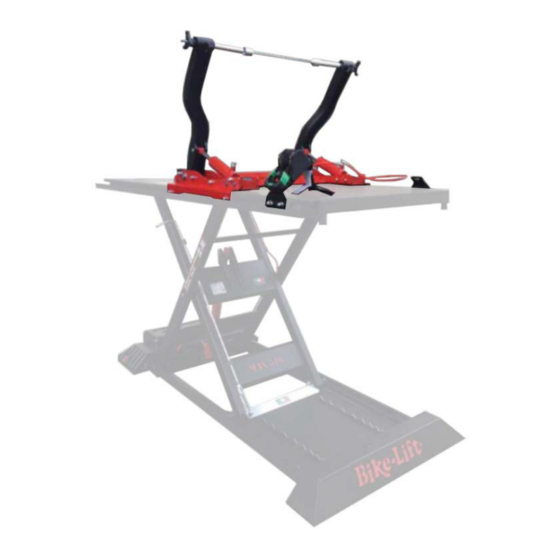
Additional lift to the lifting platform system for the maintenance and repair of motorcycles with a maximum capacity of 350 kg. The handling of Bike-Lift-Europe s.r.l lifting platforms can be done through one of the following systems: compressed air system;... - Page 11 2.3 Machine description The machine known as Additional component 516 is a suitable equipment to support motorcycles during the maintenance and repair phase in a comfortable and safe way, being fixed to the work surface of the platform. The basic parts of the lifting platform (see Figure 2) are: Figure 2 - Model of a lifting platform An automatic vise for the front wheel (yellow) The additional lifting component (blue) that can be anchored on the scissor lifting...
-
Page 12: Intended Use
2.4 Intended use Disseminate the instructions described in this chapter to all personnel involved in the preparation and use of the machine. The machine is designed for additional lifting of motorcycles for maintenance purposes. The machine has been designed and built for the specified use; a different use and non-compliance with the technical parameters set by the Manufacturer may be dangerous for the operators. -
Page 13: Technical Specifications
2.5 Technical specifications (see exploded diagram attached to this manual) TWIN ARMS MTA 516 COMPONENT – PARAMETER VALUE Maximum bearing 500 kg Maximum height 120 cm Minimum height 19 cm Safety positions number Length 220 cm Hydraulic arms max. bearing 350 kg Hydraulic arms max. -
Page 14: Safety Section
Safety section 3.1 Environmental working values The use environment of the machine must be well lit, must not present explosion hazards of any kind and must be protected from atmospheric precipitations. The machine works properly within the following values: Ambient temperature between 5° and 40° C; ... -
Page 15: Operator Protections
the sole responsibility of the Purchaser or the Machine's user. Finally, we remind you that the handling, installation, use, maintenance and putting out of service of the machine represent a source of danger if these operations are not performed in compliance with the requirements of this Manual or without the necessary caution and attention required. -
Page 16: Pictograms
During the use of the lifting platform it is very important to pay the utmost attention to the ascent and descent maneuvers. During the ascent/descent phase the operator is required to distance from the lifting platform according to the length allowed by the control panel cable. The personnel who are not in charge of using the motorcycle lifting platform must not pass or stand in the operating area of the machine. -
Page 17: Transport And Handling Section
Transport and handling section 4.1 Transport, handling and storage CAUTION: Disseminate the instructions described in this chapter to all personnel involved in the transport and handling of the machine. For safety reasons, the moving parts must be locked before transport. 4.2 Packaging and transport The machine is not sold separately from the lifting platform to which it has been connected. -
Page 18: Receipt And Check
The cardboard and wooden packaging must be lifted using a forklift truck, by inserting the forks inside the wooden supports. During the unloading phase, in any case, pay attention to the vehicles and people in transit. It is recommended that the unloading or handling operations to be carried out with a forklift truck by a single Operator equipped with workshop gloves, safety footwear and protective helmet, as required by current regulations. -
Page 19: Installation Section
Installation section The machine must be installed in compliance with the safety regulations and instructions included in this chapter. CAUTION: COMPLETELY remove the wooden sleepers located under the lifting platform by removing the fixing screws before using the machine. The machine does not need a basis, but requires a flat and horizontal floor. The floor must be able to support a minimum weight of 500 kg/m •... -
Page 20: Putting Into Service
WARNING: In the electronic or electro-hydraulic version, the lifting platform is equipped with an electronic board that transforms the low-voltage current to prevent the electrocution risk. A fuse calibrated on the amperage of the stable 230V power supply is located inside this board. It is forbidden to replace/tamper with this fuse with one of a higher resistance/amperage 5.2 Putting into service... -
Page 21: Dismantling/Scrapping Section
Dismantling/scrapping section 6.1 Dismantling Follow the Regulations regarding the materials dismantling in force in the country where the machine will be dismantled. Here are some useful indications in case you must disassemble the machine to reassemble it in other areas, store it or demolish it. 6.2 Mechanical dismantling Before proceeding with mechanical dismantling of the machine, carefully clean the whole structure (see Cleaning and Maintenance). -
Page 22: Operation Section
Operation section Figure 4 - example of installation of the MTA 516 additional component [1] of the vise [2] on the lifting platform [3] Figure 5 - general model of a lifting platform Page 23 Operating manual No. 057-2-6-0013-R0 Version 2018... -
Page 23: Loading Operations
7.1 Loading operations Before installing the vehicle on the platform it is essential to put the wheel lock (Figure 4, [2]), fix the additional component (Figure 4, [1]) check that the work surface (Figure 5, [3] ) and the additional component [1] are completely lowered and that the ascent ramp (Figure 5, [4]) is correctly positioned. -
Page 24: Operation With Both Wheels Lifted
7.1.3 Operation with both wheels lifted 8- Slide the belt joint along the guide until it reaches the rear wheel; 9- Pass the belt through the rear wheel and secure the wheel, leaving it free to lift; Proceed with the lifting control of the component arms until both wheels reach the desired height 7.2 Unloading operations 1- Make sure that the sliding guides of the MTA 516 lift are free from foreign bodies (bolts... -
Page 25: Lifting Types
7.3 Lifting types 7.3.1 COMPRESSED AIR PUMP - element code - 002 The pump is a variable calibration pressure multiplier that allows you to obtain a hydraulic flow from a pneumatic supply. DESCENT ASCENT Figure 6 – air compressed pump Read carefully the attached use and maintenance manual: Air pump C.M.O. -
Page 26: Electronic With Remote Control - Element Code 004/R 27
7.3.3 ELECTRONIC WITH REMOTE CONTROL - element code 004/R Lifting is carried out by using a remote control connected to the hydraulic pump via a remote control radio receiver. ASCENT DESCENT – Figure 8 remote control button panel with maintained action control The remote control is equipped with two buttons with maintained action that allow the ascent and descent. -
Page 27: Maintenance Section
Maintenance sectio The maintenance operation is the absolute prerogative of professional operators and specialized technicians, in compliance with the requirements of Machinery Directive 2006/42/ EC and subsequent updates. As routine maintenance, the following checks/operations must be carried out once a month: ... -
Page 28: Piston Replacement
8.3 Piston replacement In case the hydraulic piston must be replaced, proceed as follows: 1- Lower the lifting platform to the minimum height position; 2- Maintain the lowering control of the lift for another 6 seconds, to empty the oil; 3- A second operator must lift the lifting platform by hand up to about 500 mm from the ground;... -
Page 29: Cleaning
8.4 Cleaning 8.4.1 Initial cleaning The machine does not require particular initial cleaning, but it is a good practice to clean the transit areas of the motorcycles by removing the oils and dust to prevent the slip during loading. Wear water-repellent gloves. Perform the cleaning operations wearing anti-cut gloves resistant to the substances used (follow the safety data sheet). -
Page 30: Cleaning Of The Work Areas
When implementing the suggested remedy, always follow the instructions described in the Instructions to which the remedy refers. Bike-Lift Europe s.r.l. will solve all the problems that cannot be eliminated by means of the attached instructions. The motor housing (Figure 10) that activates and moves the platform is placed at the base of the piston. -
Page 31: Air Pump
8.5.1 AIR PUMP PROBLEM PROBABLE CAUSE REMEDY The pump does not The compressed air line is Verify that compressed enters the pump start closed or blocked Check that the supply pressure (air) is Air pressure too low between 6 and 10 bar The pump locks under load Dirty or clogged air filter... - Page 32 Piston inlet connection – Figure 11 compressed air pump Air inlet connection inside the pump Page 33 Operating manual No. 057-2-6-0013-R0 Version 2018...
-
Page 33: Electric Pump
Hydraulic pump problems Contact the dealer or Bike-Lift Europe s.r.l The emergency stop (red button in case of the built- Release the red button on the button in lifting platform version) panel by turning it clockwise. - Page 34 INCONVENIENT PROBABLE CAUSE REMEDY The emergency stop (red button in case of the built- Release the red button on the button in lifting platform version) panel by turning it clockwise on the button panel is inserted Operating on the Check the mains connection plug No voltage button panel the lifting...
-
Page 35: Accessories
Accessories MAX 516 BASIC EQUIPMENT PARAMETER VALUE Automatic W-36S wheel clamp 1 pc Ascent ramp 1 pc Platform supports 2 pcs Automatic RTD-6 belt 1 pc Belts for platform supports 4 pcs Page 36 Operating manual No. 057-2-6-0013-R0 Version 2018... -
Page 36: Spare Parts - Technical Drawings
SPARE PARTS - TECHNICAL DRAWINGS Page 37 Operating manual No. 057-2-6-0013-R0 Version 2018... - Page 37 Operating manual No. 057-2-6-0013-R0 Page 39 Version 2018...
- Page 38 NOTES Operating manual No. 057-2-6-0013-R0 Page 39 Version 2018...
- Page 39 NOTES Operating manual No. 057-2-6-0013-R0 Page 39 Version 2018...
Need help?
Do you have a question about the TWIN-ARMS MTA 516 and is the answer not in the manual?
Questions and answers