Advertisement
Quick Links
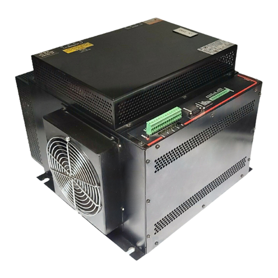
M P A - 4 6 0 A N F 3 / 8 0 3 1 B R U S H L E S S S E R V O
A M P L I F I E R
Application
This manual is designed to help you install the MaxPlus™ amplifier.
Unpacking and Inspection
Carefully unpack the amplifier and inspect it for visible damage. Check items against the
packing list. Report any missing or damaged items to your supplier.
Warranty and Service
The amplifier is warranted to be free from defects in workmanship and materials for a
period of two years from the original shipment by MTS Automation.
During the warranty period, a defective amplifier unit will be repaired or replaced as
outlined below.
Before requesting return authorization, please try to verify that the problem is within the
amplifier, and not with external devices.
To arrange for repair or replacement, please contact:
•
You must provide the model and serial number from the labels on the amplifier.
•
You must provide an explanation as to why the unit is being returned.
•
You will be issued a return authorization number which must be marked on the return shipment
and on all correspondence.
MTS Automation Customer Service
(507) 354-1616
(800) 967-1785
Monday–Friday, 8:00–4:30 Central Time
Continued on next page
1
Advertisement

Related Manuals for MTS Systems MPA-460 ANF3/8031

Summary of Contents for MTS Systems MPA-460 ANF3/8031
- Page 1 M P A - 4 6 0 A N F 3 / 8 0 3 1 B R U S H L E S S S E R V O A M P L I F I E R Application This manual is designed to help you install the MaxPlus™...
- Page 2 Warranty and Service (continued) Service Under Warranty • Return your defective unit, freight prepaid, and it will be repaired and returned within two weeks of receipt via regular UPS, freight prepaid. • Upon request, a factory-repaired replacement unit will be sent via regular prepaid UPS, within 4 working days.
- Page 3 Introduction MPA Amplifiers represent a series of amplifiers that are high performance, reliable, and efficient. The amplifiers are designed to be used with high performance brushless servo motors. Extreme care has been taken to assure robust operation. Design consideration for electrical transients have been implemented on the ac inputs and all I/O lines. MPA amplifiers operate over ac voltage ranges of 80 to 260 Vac from 45 to 65 Hz.
- Page 4 Sizes Model Continuous Amps Peak Amps MPA-05-460 MPA-09-460 MPA-15-460 MPA-25-460 MPA-35-460 MPA-50-460 MPA-75-460 MPA-100-460 Features • Efficient power conversion • High frequency switching • Resolver feedback • Simulated encoder signals • ±10 Vdc for maximum velocity or torque • 24 volt I/O for ±LIMIT, RESET, VEL/TORQUE mode •...
-
Page 5: Specifications
Specifications Parameter Specification Operating Environment: Temperature 0 to 45° C (32 to 113° F) Maximum, Ambient Humidity 0 to 95% noncondensing Input/Output Interface: Analog Signals Velocity Command Input Differential input 0 to ±10 Vdc(15 Vdc Max) Auxiliary Input Differential input 0 to ±10 Vdc(15 Vdc Max) Velocity Output 1.5 volts per 1000 rpm (default) Current Output... - Page 6 Parameter Specification MPA-15-460: Output: 15 amps continuous; 30 amps peak; peak ≤ 1 second PWM frequency 15 kHz Input: Single phase; 18 amps continuous max Three phase; 11 amps continuous max DC Bus is AC line dependent MPA-25-460: Output: 25 amps continuous; 50 amps peak; peak ≤ 1 second PWM frequency 12 kHz Input Single phase;...
- Page 7 Parameter Specification Encoder Signals: Resolution 250, 360, 400, 500, 720, 1000, 1024, 2000 and 4096 lines Accuracy: Resolver Cable Length: Max. Error: 15 foot ±20 minutes 25 foot ±20 minutes 50 foot ±30 minutes 100 foot ±40 minutes Weight: MPA-05/09-460 12 lbs.
-
Page 8: Side View
MPA-05/09/15/25/35/50-460 Mechanical Footprint NOTE .5 RECOMMENDED SIDE VIEW FRONT VIEW 14.6 13.6 11.25 Summary of Amplifier Dimensions Model A (inches) B (inches) C (inches) MPA-05/09/15-460 MPA-25/35-460 MPA-50-460 NOTE If front cover is attached, additional clearance of .2 should be allowed. - Page 9 MPA-75/100-460 Mechanical Footprint .5 RECOMMENDED 1.64 11.63 SIDE VIEW NOTE FRONT VIEW 15.2 13.6 3.15 14.6 NOTE If front cover is attached, additional clearance of .2 should be allowed.
- Page 10 Signal/Wiring Overview POWER FEEDBACK SHLD SHLD LIMIT RESET HI-BUS MOTOR FEEDBACK AMPLIFIER SHORTS CONTINUOUS CURRENT MARK ENCODER -AUX +AUX -COM +COM RESP LEAD -LIM +LIM RESET...
- Page 11 Feedback Wiring SHIELD SHIELD THERM GND THERM SWITCH SIN GND COS GND REF GND 100% Shielded Reference Frequency 2 kHz 20-25 VP-P SIN/COS 0 TO 5 V Maximum rms Winding Thermostat NOTE 100% shielded cable is foil and braid. The pairs do not have to be twisted.
- Page 12 ANF3 User Configuration Locations NOTE Never change DIP switches or jumpers with power ON.
-
Page 13: Dip Switch S2
Motors and Commutation The amplifier can commutate 4-pole, 6-pole, 8-pole, and brush motors in its standard configuration and other factory options are available. DIP switch S2 allows for configuration changes and switches one through three determine the choice. Amplifiers are shipped set for 6-pole operation. Never change the switch settings of S2 with power DIP SWITCH S2 Motor Type 8-POLE... -
Page 14: Diagnostic Indicators
Diagnostic Indicators Mark (RED) This is an output that comes ON at the resolver zero position and can be used in conjunction with alignment procedures. The zero position is about .5 degrees. Current (BI-COLOR) This is a bi-color LED that can be either red or green as a function of load. Red indicates positive torque and green indicates negative torque. - Page 15 Simulated Encoder Signals For external counting or position control, 9-pin D type female connector that has TTL complimentary outputs is provided. This simulates quadrature encoder channel A and channel B signals. A differential mark signal is also available. TYPICAL ENCODER CABLE 100% SHIELD (FOIL AND BRAID) ENCODER...
- Page 16 S4 is provided as a means to determine the resolution of the simulated encoder signals. The amplifier is configured form the factory to be 1024 lines. Lines 2000 (14-bit only) 1024 (default) 1000 4096 (14-bit only) The normal factory configuration of 2-Channel quadrature provides for output resolution of 12 bits or 4096 counts per revolution.
- Page 17 I/O Wiring and Descriptions The amplifier has four inputs and one output. These inputs and output are designed to interface to a 24 volt logic system. The amplifier is shipped so that the operation of the inputs are as follows. With no wires connected to RESET, + LIMIT, - LIMIT, or VEL/TORQUE, the amplifier is enabled and normal operation will occur in a velocity mode.
- Page 18 DIP switch S3 switches 1, 2, 3, and 4, are used for this purpose. Input Switch Number Factory Setting RESET + LIMIT – LIMIT VEL/TORQUE By setting switch 2 to the OFF position, the operation of the + LIMIT would change to be closed to run in a plus direction.
- Page 19 Analog Inputs, Outputs and Adjustments Inputs There are two analog input channels; one for command and one for auxiliary. Both of these channels are differential inputs and both are summed with a TAC feedback differential amplifier that controls velocity. ANALOG INPUT ENCODER WIRING EXAMPLE –...
- Page 20 During start-up the BAL adjustment can be used to reduce/stop any low speed CW/CCW drift caused by imbalance between the external command voltage and the amplifier. Once connected to loads, the crispness of motion (step response) and stability can be optimized with the RESP and LEAD pots.
- Page 21 Analog Inputs (Specific Interface Requirements) The analog input channels consist of differential input amplifiers to allow controllers that have differential output drivers a three wire connection that excludes potential ground loops. When differential modes of operation are used, the command or auxiliary input is based on 5 volts equaling maximum input and the analog ground from the external controller must be connected to the MPA drives GND connection.
- Page 22 Resolution R-D Converter SW2 is used to set the resolution of the resolver to digital converter. The amplifier is configured from the factory for 12-bit mode. Mode 12-bit (default) 14-bit The motor speed and TAC gradients are affected by these settings. Mode Maximum Speed 12-bit...
- Page 23 DIP Switch SW3 - Velocity Signal Processing REF– 3 1 REF+ TP23 R155 200K U39A R154 – LM358 R159 R137 R157 R158 R156 200K 390K 100K C109 .022M .047M EXTERNAL BRUSHLESS R138 R139 INTERNAL RESOLVER...
-
Page 24: Default Dip Switch Settings
Default DIP Switch Settings Comment Lead/Lag 12-bit mode Commutation Encoder (1024L) SW1 determines the lead lag compensation networks, and is usually only modified to achieve stability on high inertia loads. SW2 is used to alter the operation of the R-D converter and is preset to the 12-bit mode. This switch setting is only altered to achieve higher line density simulated encoder selections or higher TAC gradients. - Page 25 Lead/Lag Compensation SW1 is provided as a means to alter the amplifier's lead/lag network. Switches 1-4 can be switched ON to allow for forward compensation of the TAC signal in the summing node of the differential amplifier used for the velocity loop. This signal had the effect of damping the loop, and is an effective method to control large inertia loads.
-
Page 26: Overspeed Shut Down
DIP Switch SW1 — Lead/Lag Compensation TACH U31A .047M TL084A .22M .47M .47M LEAD .22M .047M 200K 200K 200K CURRENT COMMAND 200K 200K C135 RESP BALANCE LM358 5.1K XRB1C Overspeed Shut Down The overspeed shut down circuit converts the TAC gradient into an absolute value for comparison to a preset value. - Page 27 AC Input and Internal Protection A branch circuit disconnect must be provided in front of the amplifier. For the 460 volt models, either single phase or three phase power can be applied. Model Single Phase Three Phase MPA-05-460 6 amps 4 amps MPA-09-460 11 amps...
- Page 28 Grounding The ac supply source for the amplifier is supposed to be bonded to earth ground. Typical WYE Secondary L1 (HOT) L2 (HOT) L3 (HOT) EARTH GROUND Typical Delta Secondary L1 (HOT) L2 (HOT) L3 (HOT) EARTH GROUND These are the two most typical transformer configurations and failure to ground these properly could void warranty.
- Page 29 The MPA amplifier does not care where the earth ground is. This example is a delta secondary. Delta Secondary L1 (HOT) L3 (HOT) L2 (NEUTRAL) EARTH GROUND In this example L2 became ground.
- Page 30 Power/Grounding Requirements The following information covers the grounding requirements of 3-phase servo amplifiers manufactured by MTS Automation. It has been found when an amplifier has been connected to a transformer with an ungrounded secondary, premature amplifier failure will occur. The 3-phase MPA amplifiers require the AC power (L1, L2, L3, and Ground) be derived from a transformer which has it's secondary intentionally bonded to earth ground.
- Page 31 Example 1 shows a typical factory configuration. It shows a ungrounded delta secondary and there is existing equipment already running. on line. This equipment could be simple 3-phase induction motors where an ungrounded secondary is not an issue. However, before a 3-phase MPA amplifier, or a machine utilizing 3-phase amplifiers, can be connected, an isolation transformer, with a grounded secondary must be installed.
- Page 32 Stator Wiring The locked rotor stator current is equal to the amplifiers continuous rating and for either low speed or locked rotor conditions the stator must withstand this continuous rating. Derating the stator wiring for three phase operation should not be done. Model Locked Rotor MPA-05-460...
- Page 33 Shunt Loads Regenerative energy during deceleration causes the normal voltage on the drives bus to increase. The amount of energy is application dependent and relates to total inertia. In general the drives internal shunt load can dissipate this energy within the constraint that the load inertia is not more than 20 times that of the rotor but, this is a guideline.
-
Page 34: Thermal Characteristics
Thermal Characteristics The drives are specified to operate at a 45° C ambient. This is not a maximum safe operating specification. There are no parts in the drive that cannot operate at a 60° C temperature. The absolute maximum temperatures that the drive can operate at are determined by thermal switches on the bridge switch power devices (IGBT's) and on the shunt loads. - Page 35 Shunt/Amplifier Wiring...
- Page 36 EXS-50/100-460 Mechanical Footprint 16.0" 15.5" 0.5" 8.5" 1.0" 9.5" 5.6"...
- Page 37 External Inductors External inductors can be placed in the amplifier R, S and T leads to assure that the minimum inductance specification is assured. The MPA-05/09/15 models all have 2mH drum core inductors installed under the top cover. These versions do not need external inductors to protect the motor.
- Page 38 Inductor Mechanical Footprint (loose parts) Typical: IND-100-.5mH 5.25" 4.81" .44" 3.85" 4.27" .42" 6.35"...
- Page 39 Typical: IND-25-460-2mH 3.75” Clearance 3.39" 3.10" .20" .29" 3.30" .25" 3.05" 4.60"...
- Page 40 "-S" Separated Supply Option The -S option amplifier allows for the removal of the dc voltages from the power devices within the amplifier that form the outputs RST. This is accomplished by removing the main ac (bridge) input. The amplifier should be disabled prior to the removal of power and should not be enabled until this power is restored.
- Page 41 Typical "–S" Three Phase 460V Amplifiers...
- Page 42 "-T" Brushless TAC Option The MPA amplifiers use resolver feedback. The resolver provides positional information for commutation of the motor, simulated encoder signals and a velocity signal for the amplifier when the velocity mode is selected. In some instances, the quality of the velocity signal derived from the resolver to digital converter compromises performance because of 2-Pole cyclic position ripple.
- Page 43 Typical Motor Connector BROWN / WHITE TAC RET PINK –12 ORANGE / WHITE GREEN SHIELD SHLD BLACK / WHITE BLUE / WHITE BLUE YELLOW BLACK YELLOW / WHITE RED / WHITE MOTOR MOTOR STATOR POWER WIRING RESOLVER BRUSHLESS TAC The amplifier is further changed so that the brushless TAC signal is processed through the amplifiers normal velocity paths.
- Page 44 Start-Up Once normal wiring is verified, power can be applied to the amplifier. Assure the DIP switch and jumpers are set as required. Default settings are for 6 pole motors on the amplifiers. Inputs Reset, +Limit, and -Limit are not going to disable the amplifier if they are not connected.
-
Page 45: Typical Wiring
Typical Wiring...
Need help?
Do you have a question about the MPA-460 ANF3/8031 and is the answer not in the manual?
Questions and answers