Table of Contents
Advertisement
Quick Links
www.reersafety.com
SAFEGATE M SG BOX RST
GENERAL
The SAFEGATE M SG BOX RST modules are accessory devices designed to make the wiring of the
SAFEGATE S / SAFEGATE TRX-S, barriers fast and safe, as well as provide the main controls
necessary for their operation close to the protected gate.
In addition to the safety relays with guided contacts piloted and monitored by the light curtain, terminal
blocks for connecting the cables, jumpers and dip-switches for the configuration of the barrier itself.
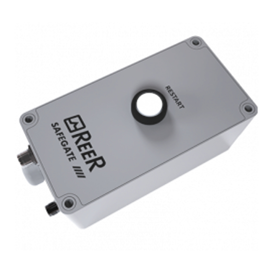
DESCRIPTION
M SG BOX RST is characterized by:
Luminous push-button for restart and output status indication.
Connectors for wiring the box to the barrier:
12 M12-8 poles male for TRX-S Active Element (or SAFEGATE S Receiver);
12 M12-5 poles female for SAFEGATE S Emitter.
Fairlead for the connections toward the machine of:
power supply;
connection with the output contacts of the internal safety relays and relative EDM;
output signals which indicate the status of the safety light curtain.
KEY SELECTOR FOR
CONNECTOR
EMITTER
(SAFEGATE S)
CABLE
FAIRLEAD
8
INTERCONNECTION MODULES
OVERRIDE
Figure 4 - M SG BOX RST – Connections and signals
M SG BOX RST
CONNECTOR
ACTIVE ELEMENT
(SAFEGATE TRX-S)
RECEIVER
(SAFEGATE S)
8541290 01 • 24/03/2020 • Rev.0
Advertisement
Table of Contents

Related Manuals for Reer SAFEGATE M SG BOX RST


Summary of Contents for Reer SAFEGATE M SG BOX RST
- Page 1 SAFEGATE M SG BOX RST GENERAL The SAFEGATE M SG BOX RST modules are accessory devices designed to make the wiring of the SAFEGATE S / SAFEGATE TRX-S, barriers fast and safe, as well as provide the main controls necessary for their operation close to the protected gate.
- Page 2 M SG BOX RST www.reersafety.com CONFIGURATION The configuration of the operating modes is described below. This configuration is performed following the descriptions of the tables below, by setting the various jumper, connectors and dip-switches located on the main board. Figure 5 – Main board 8541290 01 •...
- Page 3 www.reersafety.com M SG BOX RST SELECTION OF OPERATION MODES (DIP-SWITCH SW1-SW2) Automatic Mode Automatic Mode without EDM DIP-SWITCH █ █ █ █ █ █ █ █ █ DIP-SWITCH █ █ █ █ █ █ █ Automatic Mode with EDM internal relays DIP-SWITCH █...
- Page 4 M SG BOX RST www.reersafety.com SELECTION OF OPERATION MODES (DIP-SWITCH SW1-SW2) Modalità Manuale Manual Mode without EDM DIP-SWITCH █ █ █ █ █ █ █ █ DIP-SWITCH Manual Mode without EDM internal relays DIP-SWITCH █ █ █ █ █ █ █...
- Page 5 www.reersafety.com M SG BOX RST INSTALLATION AND ELECTRIC CONNECTIONS The M SG BOX RST modules can be fixed to the wall, using the proper plastic brackets inserted in the holes placed on the box rear side corners. These brackets can easily rotate to reach 90°. ...
- Page 6 M SG BOX RST www.reersafety.com SIGNALS SIGNAL CONDITION MEANING Outputs active OUTPUT STATUS (White) Light curtain occupied: outputs disabled (Low intensity blinking) SAFETY RELAYS TECHNICAL DATA The M SG BOX RST module uses two safety relays with guided contacts for the output circuit. These relays are specified by the manufacturer for voltages and currents greater than those indicated in the technical data;...
- Page 7 ReeR S.p.A. therefore declines any responsibility for all and anything resulting from failure to comply with all or some of the aforesaid instructions. Characteristics are subject to change without prior notice. No part of this document may be reproduced unless authorised by ReeR. 8541290 01 • 24/03/2020 • Rev.0...
- Page 8 www.reersafety.com M SG BOX RST All R R Safegate manuals and configuration software are available at www.reersafety.com/download/safegate 8541290 01 • 24/03/2020 • Rev.0...
Need help?
Do you have a question about the SAFEGATE M SG BOX RST and is the answer not in the manual?
Questions and answers