Advertisement
SAFETY INTERFACE
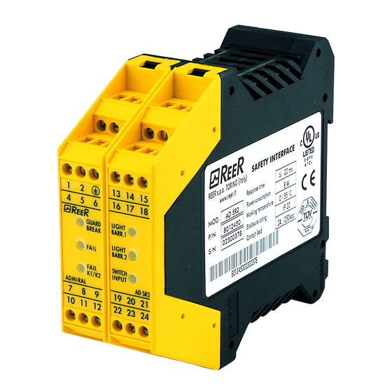
AD SR2
INSTALLATION
USE AND
MAINTENANCE HANDBOOK
INDICE
INTRODUCTION................................................................................................................... 3
OPERATING MODES........................................................................................................... 4
INSTALLATION AND ELECTRICAL CONNECTIONS...................................................... 7
DIMENSIONS...................................................................................................................... 10
TECHNICAL DATA ............................................................................................................. 10
WARRANTY ........................................................................................................................ 11
Advertisement

Subscribe to Our Youtube Channel
Related Manuals for Reer AD SR2


Summary of Contents for Reer AD SR2
-
Page 1: Table Of Contents
SAFETY INTERFACE AD SR2 INSTALLATION USE AND MAINTENANCE HANDBOOK INDICE INTRODUCTION........................3 OPERATING MODES......................4 INSTALLATION AND ELECTRICAL CONNECTIONS............7 DIMENSIONS........................10 TECHNICAL DATA ......................10 WARRANTY ........................11... -
Page 3: Introduction
(connected to its outputs) and uses the input of the K1/K2 feedback to check that these operate in safety. The AD SR2 interface, when connected to one (or two) type 4 photoelectric safety barriers certified to IEC 61496 – 1/2 standard, equipped with two built-in solid-state PNP outputs, conforms to ESPE (Electro-Sensitive Protective Equipment) type 4. -
Page 4: Operating Modes
OPERATING MODES AUTOMATIC In this operating mode, the outputs of the safety interface follow the status of the light curtain • with the protected area free (outputs of the light curtain active), the relay outputs of the interface are active. •... - Page 5 Once the protected area has been occupied, the relay outputs are de- activated. The sequence described above must be repeated in order to re-activate these. The RESTART command is active with a voltage of 24 Vdc. The minimum duration of the command is 300 ms. CONNECT INPUTS 8-9-11 TO +24Vdc AND INPUT 12 TO 0Vdc IF NOT USED Figure 2 CONNECTION OF EXTERNAL CONTACTORS K1 and K2...
- Page 6 K1/K2 malfunction detected FAIL FAIL output relays open SAFETY K1/K2 SWITCH K1/K2 Correct functioning ADMIRAL ADMIRAL AD SR2 AD SR2 Barrier 1 clear LIGHT Green Barrier 1 intercepted, output relays open BARR1 Barrier 2 clear 7 8 9 19 20 21 LIGHT...
-
Page 7: Installation And Electrical Connections
INSTALLATION AND ELECTRICAL CONNECTIONS The AD SR2 safety interface must be installed in an environment with at least IP54 protection. The voltage supplied to the AD SR2 interface must be of the FELV (Functional Extra Low Voltage) 24VDC ± ± 20% type. - Page 8 • To calculate the SYSTEM RESTART DELAY, add the restart delay for any external K1/K2 contactors to the AD SR2 interface restart delay (300ms). • In case of manual operation, an external N/O switch can be used that, when temporarily closed, generates the RESTART command.
- Page 9 Use of K1 and K2 auxiliary contact elements. For loads with higher voltage and current characteristics than those indicated in the table above, use of auxiliary external relays or contactors suitable for the load to be controlled is recommended. If the K1 K2 Feedback is used, The K1 and K2 auxiliary contactors or relays must be of the guided contact safety type.
-
Page 10: Dimensions
DIMENSIONS TECHNICAL DATA 24 ± 20% Supply voltage 8 max Power requirement 2 N.A contacts, 1 N.C contact (2A; 250V) Relay Output 20 max Response time Manual or Automatic, selectable from terminal block Operating modes 1 N.A contact, 1 N.C contact (20mA; 24VDC) External relay control To terminal block with protection Connections... -
Page 11: Warranty
Precise, complete compliance with all the rules, instructions and prohibitions indicated in this handbook is an essential requirement for correct functioning of the safety interface. REER s.p.a. therefore declines any responsibility for all and anything resulting from failure to comply, even partially, with such indications.
Need help?
Do you have a question about the AD SR2 and is the answer not in the manual?
Questions and answers