Table of Contents
Advertisement
Advertisement
Table of Contents

Related Manuals for Honeywell NOTIFIER AM-8000


Summary of Contents for Honeywell NOTIFIER AM-8000
- Page 1 AM-8000 Installation manual Intelligent Addressable Fire detection...
- Page 3 INDEX Limits of Fire Detection Systems EN 54 : Informations – Option with Requirements General Description INSTALLATION: Dimensions for wall assembly Front Panel indications Electrical features Earthing Mains power supply Power Supply Battery Charger section Batteries Power supply and battery operation Mains and Batteries connection User power supply output Fuse list...
- Page 4 NOTE: Do not try to install the control unit and devices connected without reading this manual. DETECTION SYSTEM LIMITS An alarm or fire detection system can be very useful for the prompt warning of any dangerous event, such as fire, a robbery or a simple burglary, in some cases it can automatically manage events (transmission of messages for room evacuation, automatic fire-extinguishing, TVCC system interface, access route or door blockage, automatic warning to authorities, etc.), but in any case, it does not ensure protection against damages to propriety or...
- Page 5 EN 54 : Informations The AM-8000 control unit has a maximum capacity of : 636 sensors EN54-2 13.7 and 636 addressable modules . EN54 Max 512 If this function is not appropriately used, it can contravene the EN54 Sensors / Manual requirements.
-
Page 6: General Description
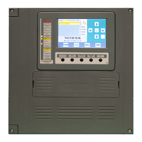
GENERAL DESCRIPTION control unit is a fire detection control unit manufactured in conformity with the EN.54.2 and EN.54.4 rules. AM-8000 Technical features : Multi-microprocessor system LCD-8000-L / LCD-8000-F with display TFT 7” (800 x 480 with backlit ) and 256 colors and touch-screen with keyboard simulation to program and configure the system. -
Page 7: Installation
Installation Dimensions for wall assembly External sizes (L) x (H) x 240 403mm 408mm mm ( View from High View from back View from back View from low Moreover, if the control unit must The control unit must be installed to the be installed to the wall beside a wall so as to allow a clear view of the 400mm... - Page 8 Extractable labels on the front panel AM-8000 control unit is provided with extractable labels to indicate the functions Status via LED and some function buttons. AM-8000 Manuale di installazione PAGE - 5 AM8000_manu-inst Doc. 160.1-AM8000-ITA Rev A.3 NOTIFIER ITALIA...
-
Page 9: Electrical Features
ELECTRICAL FEATURES Operation temperature: - 5° C ÷ + 40°C. Relative humidity: 10 % ÷ 93 % (without condensation). Storage temperature: - 10°C÷ + 50°C. Earthing The earthling system must be performed in conformity with CEI and ISPELS rules or rules valid in the country where the panel is installed. -
Page 10: Batteries Installation
BATTERIES Installation Power supply and battery operation The main microprocessor of the control unit periodically checks the state of the main AC power supply source, batteries and the recharging circuit. The control unit will automatically switch on the stand-by battery source when AC mains fails. When the control unit operates through AC mains, the main microprocessor controls the battery charger output and the presence of them. - Page 11 Mains and Batteries connection The 230 Vac mains power supply cable must preferably pass near the relevant terminal block. The connection to the 230 Vac power supply mains must be performed through three-conductor cable (phase- neuter- earth). The identification of the earth conductor coming from the mains must be performed on the CNAL terminal block (refer to basic board topography) and must be fixed at the cabinet by means of cable –tightening strip so that it cannot be accidentally stripped off from the terminal block.
- Page 12 Current consumption from battery Current from battery in Normal Condition in the absence of mains voltage 230Vac: CPU-8000 Card at nominal voltage (24Vdc): 83mA if the Card is connected to LCD-8000-L (or LCD- 8000-F); 91mA if the Card is not connected to LCD. ...
-
Page 13: Relay Outputs
Relay outputs FUNCTION CHARACTERISTICS 1 contact controlled by 24Vcc / 2A resistive Siren selectable through Jumper JALL Max 2A resistive 30 Vdc, NA-NC General Alarm refer to basic board topography General Fault selectable through Jumper Max 2A resistive 30 Vdc, NA-NC JGST refer to basic board topography USR1... -
Page 14: Short Circuit
Sounder connection - controlled output Siren output connections ( refer to basic board topography) Polarized devices (electronic sirens, etc.) 47 K ¼ W NOTE: Connect the 47K , ¼ W EOL resistor only on last sounder of the line Non-polarized devices (Bells, relays, etc.) ATTENTION: 47 K Polarity... -
Page 15: System Components
SYSTEM COMPONENTS Black Box Each Black Box is equipped of one CPU card and can contain up to 2 Loop Interface cards ( LIB-8000 ) Each LIB card can drive up to 2 ADV loop Each ADV Loop line can connect up to 159 detector and 159 Modules in Advanced protocol or 99+99 in CLIP mode. - Page 16 CNA terminal block N° description Function Note Phase 230Vac mains Power Eatrh Fused with 3,15 AL Neutral CNU terminal block N° Name description Note Fused with 4 A fuse +24V USR GND USR Sounder/ Siren (positive in Fused with 1,35A resettable fuse (this is a non alarm) EOL resistor = 47KΩ...
- Page 17 DIP SWITCH on CPU CARD Download Tech ADDRESS config. Load conf. use only Upgrade Black Box n.1 Black Box n.2 Black Box n.3 Black Box n.4 Black Box n.5 Black Box n.6 Black Box n.7 Black Box n.8 Box ID Dip 5 = ON proper from USB key loads configuration...
- Page 18 NOTE: The two CPU cards of the two available LCD models ( LCD-800-F and LCD-8000-L differs in the component and in the software, but maintain all end-user Connectors and Dip Switches in the same positions and with the same pin-out. AM-8000 Manuale di installazione PAGE - 15...
- Page 19 DIP SWITCH settings on LCD CARD ADDRESS OFF only Upgrade LCD n.1 Normal Operation LCD n.2 Normal Operation LCD n.3 Normal Operation LCD n.4 Normal Operation LCD n.5 Normal Operation LCD n.6 Normal Operation LCD n.7 Normal Operation LCD n.8 Normal Operation ID: proper configuration Off Off...
- Page 20 LCD-8000-L /F installed along the CAN-Bus Network : use CAN-LCD-8000 CARD This card is necessary when the LCD is not installed in the same cabinet with the AM-8000 CPU AM-8000 Manuale di installazione PAGE - 17 AM8000_manu-inst Doc. 160.1-AM8000-ITA Rev A.3 NOTIFIER ITALIA...
- Page 21 Display -Si TFT 7”wide (800x3rgbx480) with resistive touch screen. Antiglare surface. LED Backlite software controlled. Keyboard 5 buttons + touch screen Buzzer Monotone Real Time Clock Internal RTC with replaceable battery Power Supply When installed inside the Black Box, the LCD-8000 is powered from the Panel with a flat Cable (max 2 mt)) When installed outside the Black Box , the CAN-LCD-8000 card must be used and an external power ( min 18Vcc a - max 40Vcc ) must be provided Operating Temperature...
- Page 22 AM-8000 Manuale di installazione PAGE - 19 AM8000_manu-inst Doc. 160.1-AM8000-ITA Rev A.3 NOTIFIER ITALIA...
- Page 23 System Network Wiring Both LCD-8000-F and LCD-8000-L units are integral part of the AM- EN54-2 8000 system. This implies that are “not only” events repeaters, but EN54 also enable the operator to perform all EN 54.2 mandatory 8.2.6 - 12.5.3 functions like configuration, test, disabling etc.
- Page 24 System Wiring Example AM-8000 Manuale di installazione PAGE - 21 AM8000_manu-inst Doc. 160.1-AM8000-ITA Rev A.3 NOTIFIER ITALIA...
-
Page 25: Communication Cable
CAN Bus wiring : CABLES Communication Cable Cable used for CAN Bus connection must be : Twisted pair – Shielded – Impedance: 120 Ohm Shield wire have to be connected to the negative terminal on both side to guarantee the reference continuity. Suggested cables are : Double pair for both CAN-Bus + Power supply: Belden 3082 A Multi-Conductor (18 AWG for CAN-Bus + 15 AWG for Power supply) -
Page 26: Dip Switch Sw1
LIB-8000 Card DIP SWTCHES TO PROGRAM LIB NUMBER DIP SWITCH SW1 LIB1 LIB2 LIB-8000 CNU terminal Block N° Description Characteristics Note Fault relay “Common” Max 30V 1A Select N.O./N.C. with Fault relay N.C./ N.O. JGST Jumper Alarm Relay “Common” Max 30V 1A Select N.O./N.C. - Page 27 Communication lines with Detectors / Modules The AM-8000 control unit communicates with intelligent detection and control devices which are addressable through a 2 wire line. The line can be connected to respect the specifications relevant to the signalling circuit lines of the STYLE 4 (open line) and STYLE 6 (closed line).
- Page 28 MODULE AND SENSOR CONNECTION For the specific device connections , please refer to : “Analogue system device installation manual” document : M-199.1-SCH-ITA or M-199.1-SCH-ENG by Notifier Italia. Example of closed line (style 6 or Loop) M700KI M700KI M700KI “B” SIDE “A”...
- Page 29 Test procedure for analogue system lines Before powering the control unit lines, check the following values: NOTE: A DIGITAL MULTI METER IS REQUIRED Line resistance Positive Side B Negative Side A The direct current resistance of the negative wire of the loop SHALL NOT exceed 20 Ohm. The measurement must be performed by disconnecting the channels “A”...
- Page 30 System Test and Commissioning The Control unit installation must be performed after having carefully read the instructions contained in the installation manual and the programming manual. Once mechanical installation of the control unit has been completed, perform the following operations: ...
- Page 31 SYSTEM PERIODICAL MAINTENANCE Check that the green led “POWER OK” is on Check that all other control unit leds are off Press the function TEST key on the LCD and enter the level 2 password to access the “TEST” menu. Use the arrow keys ...
- Page 32 POWER SUPPLY – Current calculation The power supply must be able to continuously power all the internal system devices (and all external devices) during the stand-by period, that is in NON-alarm conditions. Use the table A to calculate the load in stand-by conditions. Use the table B to calculate the additional current which is necessary in Alarm conditions A 24 Vcc internal power supply for a total of 4 Ampere is available on the power supply for the system operation NORMALcondition...
- Page 33 Table 2 PERIPHERALS POWERD BY LOOPS Device type Quantity Current Total in Current Total in normal condition Alarm condition Detectors serie NFX Detectors serie 700 Single Modules serie 700 Double Modules serie 700 Modules serie MA MMX-10 N CMX-10 R Isolation modules Addressable Sounders (Power from loop)
- Page 34 Summary of Current consumption of Loop devices: Device Current NOTE Normal Alarm SDX-751ME 300 μA 6,5 mA SDX-751TEM 300 μA 7 mA FDX-551E 300 μA 7 mA FDX-551HTE 300 μA 7 mA NFXI-OPT 300 μA 4 mA NFXI-TDIFF 300 μA 4 mA NFXI-TFIX 58/78 300 μA...
- Page 35 E-mail: notifier@notifier.it A Honeywell company Every care has been taken in the preparation of this data sheet but no liability can be accepted for the use of the information therein. Design features may be changed or amended without prior notice.
Need help?
Do you have a question about the NOTIFIER AM-8000 and is the answer not in the manual?
Questions and answers