Table of Contents
Advertisement
Available languages
Available languages
Quick Links
Advertisement
Table of Contents

Related Manuals for Tecnodom M Series


Summary of Contents for Tecnodom M Series
- Page 1 Vetrine refrigerate - Refrigerated serve-over displays - Refrigèere mueble - Kuehl vitrinen MANUALE D’USO E MANUTENZIONE USER AND MAINTENANCE MANUAL MANUEL D’INSTALLATION E DE FONCTIONNEMENT BEDIENUNGS- UND WARTUNGSANLEITUNG Rev. 1_2018 - del 01/2018 Cod. LISERIEMN...
- Page 2 IT | SERIE M | Manuale d’uso e manutenzione Benvenuto Istruzioni originali Vi ringraziamo per aver scelto un nostro prodotto. ATTENZIONE Siete invitati a leggere attentamente il presente manuale per assicurarvi l'utilizzo LEGGERE ISTRUZIONI ottimale della Vostra attrezzatura. ITALIANO - RAEE - Gestione rifiuti apparecchiature elettriche ed elettroniche - Il simbolo del bidone barrato posto sul prodotto o sulla documentazione del manuale d’uso, indica che il prodotto è...
-
Page 3: Table Of Contents
SERIE M | Manuale d’uso e manutenzione | IT Sommario INTRODUZIONE Pag.4 USO DEL MANUALE Pag.4 CONSERVAZIONE DEL MANUALE Pag.4 DESCRIZIONE DEL MOBILE REFRIGERATO Pag.5 1 POSIZIONAMENTO DEL MOBILE Pag.6 1.1 TRASPORTO Pag.6 1.2 SCARICO MOBILE / DIMENSIONI / PESI Pag.6 1.3 IMBALLO Pag.6... -
Page 4: Uso Del Manuale
IT | SERIE M | Manuale d’uso e manutenzione INTRODUZIONE Gli apparecchi denominati Banchi Refrigerati della “linea SERIE M” comprendenti i modelli “800 - 900 - 1000” sono stati re- alizzati rispettando l’insieme delle norme comunitarie riguardanti la libera circolazione di prodotti industraili e commerciali nei paesi UE. -
Page 5: Descrizione Del Mobile Refrigerato
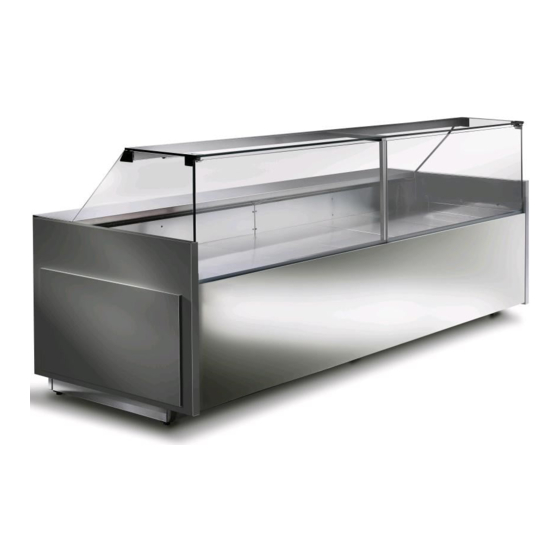
SERIE M | Manuale d’uso e manutenzione | IT DESCRIZIONE DEL MOBILE REFRIGERATO Il presente manuale d'uso fa riferimento ad una “Vetrina refrigerata” nella versione di tipo a servizio assistito per la conservazione e la vendita di prodotto fresco. Il modello SERIE M 800 comprende: Modello SERIE M 800 VD (Profondita' 90 cm): mobile ventilato con vetro frontale dritto apribile. -
Page 6: Posizionamento Del Mobile
IT | SERIE M | Manuale d’uso e manutenzione 1 POSIZIONAMENTO DEL MOBILE Prima di scaricare/caricare e posizionare il mobile all’interno del locale di vendita, si prega di consultare attentamente il manuale nelle varie sezioni riguardanti lo scarico/carico del mobile, lunghezze, pesi, vaschetta di scarico acqua di condensa, regolazione dei piedini, regolazione del pannello di comando elettronico. -
Page 7: Vaschetta Scarico Acqua Condensa Collegamento Scarico
SERIE M | Manuale d’uso e manutenzione | IT ATTENZIONE In modo da permettere un buon funzionamento del mobile frigorifero, prestare attenzione alle seguenti indicazioni: Non posizionare il mobile con esposizione diretta ai raggi solari ed a tutte le altre forme di irraggiamento, quali •... -
Page 8: Mobile Con Unita' Condensatrice Incorporata
IT | SERIE M | Manuale d’uso e manutenzione I mobili con unità remota vengono forniti solo con il sifone di scarico senza la vaschetta acqua di condensa (opzionale). Sarà cura del cliente provvedere al collegamento per lo scarico dell’acqua. È importante che immediatamente fuori dalla vasca sia presente un sifone che blocchi la fuoriuscita dell'aria fredda e l'ingresso di odori inopportuni. -
Page 9: Messa In Funzione Ed Utilizzo
SERIE M | Manuale d’uso e manutenzione | IT È necessario che la sezione del cavo di alimentazione sia adeguata alla potenza assorbita dal gruppo. È obbligatorio a termine di legge la messa a terra dell’impianto, pertanto è necessario collegarlo ad un efficiente impianto di messa a terra. Se il cavo di alimentazione è... -
Page 10: Pulizia
IT | SERIE M | Manuale d’uso e manutenzione 3 PULIZIA 3.1 PULIZIA DEL MOBILE FRIGORIFERO È indispensabile tenere pulito il mobile frigorifero. Tutte le operazioni di pulizia devono essere eseguite con unità ferma, togliendo tensione sia al mobile refrigerato che all'unità condensatrice. Per queste operazioni si consiglia di utilizzare guanti da lavoro come protezione È... -
Page 11: Raccomandazioni Ed Avvertenze
SERIE M | Manuale d’uso e manutenzione | IT 4 RACCOMANDAZIONI ED AVVERTENZE ATTENZIONE La presente attrezzatura professionale può essere utilizzata e pulita solo da soggetti maggiorenni (> 18 anni in Europa o altri limiti definiti dal compendio normativo locale) aventi condizioni psico-fisiche normali e adeguatamente addestrati e formati in materia di tutela della salute e sicurezza nei luoghi di lavoro. - Page 12 IT | SERIE M | Manuale d’uso e manutenzione ATTENZIONE Per il corretto funzionamento del mobile, è necessario , che i prodotti contenuti siano disposti in modo da non ostacolare la libera circolazione dell’aria refrigerata all’interno del mobile stesso. Nella parte interna di ogni spalla laterale del mobile è posizionato un fianco laterale in vetro. Su di esso è posizionata una linea rossa adesiva che delimita il max carico di prodotto che si può...
-
Page 13: Canalizzazione
SERIE M | Manuale d’uso e manutenzione | IT 5 CANALIZZAZIONE Tutte le operazioni riportate in questo capitolo devono essere eseguite con unità ferma, togliendo tensione sia al mobile stesso che all'unità condensatrice. Tali operazioni devono essere eseguite esclusivamente da personale abilitato e specializzato. 5.1 FASI CHE PRECEDONO LA CANALIZZAZIONE Togliere l’imballo del mobile;... -
Page 14: Punti Fissaggio Tra Le Sezioni
IT | SERIE M | Manuale d’uso e manutenzione 5.3 PUNTI FISSAGGIO TRA LE SEZIONI Dopo aver terminato le operazioni descritte nel paragrafo "5.2 ISTRUZIONE PER LA CANALIZZAZIONE" Pag. 13, avvicinare le sezioni del mobile, fissare le 2 sezioni con le viti (da A alla C) nelle apposite predisposi- zioni al fissaggio. -
Page 15: Manutenzione - Gestione Rifiuti - Smaltimento Materiali
SERIE M | Manuale d’uso e manutenzione | IT 6 MANUTENZIONE - GESTIONE RIFIUTI - SMALTIMENTO MATERIALI Tutte le operazioni di manutenzioni e riparazioni del mobile Frigorifero devono essere eseguite con unità ferma, togliendo tensione sia al mobile stesso che all'unità condensatrice. Tali operazioni devono essere eseguite esclusivamente da personale abilitato e specializzato. -
Page 16: Sostituzione Motoventilatore
IT | SERIE M | Manuale d’uso e manutenzione 6.4 SOSTITUZIONE MOTOVENTILATORE Il mobile frigorifero è dotato di motoventilatori, se si necessita la sostituzione, togliere la tensione di alimentazione, verificare la targhetta dati tecnici del motoventilatore e sostituirlo con uno di identica potenza, voltaggio e frequenza. -
Page 17: Ordinare Le Parti Di Ricambio
SERIE M | Manuale d’uso e manutenzione | IT 6.8 ORDINARE LE PARTI DI RICAMBIO Dopo aver verificato il problema con un tecnico specializzato, comunicare in modo chiaro ai nostri uffici commerciali: • Modello del mobile frigorifero • Numero di matricola del mobile frigorifero •... -
Page 18: Pannelli Comando
IT | SERIE M | Manuale d’uso e manutenzione 7 PANNELLI COMANDO EW 961 - EW 974 controllori elettronici per unità refrigeranti ATTENZIONE LEGGERE ISTRUZIONI Leggere attentamente il seguente capitolo allegato al prodotto e le norme di sicurezza in esso conte- nute prima di mettere in funzione l’apparecchio! Conservare il manuale d'istruzioni accuratamente! TASTI E LED SET / SET Ridotto... - Page 19 SERIE M | Manuale d’uso e manutenzione | IT ACCESSO E USO DEI MENU Le risorse sono organizzate in 2 menu ai quali si accede nel modo seguente: • menu “Stato Macchina”: premendo e rilasciando il tasto • menu “Programmazione”: premendo il tasto per oltre 5 secondi.
- Page 20 IT | SERIE M | Manuale d’uso e manutenzione ALLARMI Label Guasto Causa Effetti Risoluzione Problema • Visualizzazione label E1 • Icona Allarme Fissa • controllare il tipo di sonda • lettura di valori al di fuori del • Disabilitazione del regolatore (NTC) Sonda1 guasta range di funzionamento...
- Page 21 SERIE M | Manuale d’uso e manutenzione | IT UTILIZZO DELLA COPY CARD La Copy Card è un accessorio che, connesso alla porta seriale di tipo TTL, consente la programmazione rapida dei parametri dello strumento (carico e scarico di una mappa parametri in uno o più strumenti dello stesso tipo). Le operazioni di upload (label UL) e di formattazione della chiavetta (label Fr) si effettuano nel seguente modo: Dopo aver inserito la password “PA2”, scorrere con i tasti fino a visualizzare la funzione desiderata (es.
- Page 22 IT | SERIE M | Manuale d’uso e manutenzione Le sonde non sono caratterizzate da alcuna polarità di inserzione e possono essere allungate utilizzando del normale cavo bipolare (si fa presente che l’allungamento delle sonde grava sul comportamento dello strumento dal punto di vista della compatibilità elettromagnetica EMC: va dedicata estrema cura al cablaggio).
- Page 23 SERIE M | Manuale d’uso e manutenzione | IT NOTA 1: verificare l’alimentazione dichiarata sull’etichetta dello strumento; consultare l’Ufficio commerciale per disponibiltà portate relé, alimentazioni e sonde PTC. NOTA: Le caratteristiche tecniche, riportate nel presente documento, inerenti la misura (range, accuratezza, risoluzione, ecc.) si riferiscono allo strumen- to in senso stretto, e non ad eventuali accessori in dotazione quali, ad esempio, le sonde.
- Page 24 IT | SERIE M | Manuale d’uso e manutenzione Power-on Alarm Override. Tempo di esclusione allarmi all’accensione dello strumento, dopo mancanza di tensione. defrost Alarm Override. Tempo di esclusione allarmi di temperatura dopo lo sbrinamento. Ritardo segnalazione allarme dopo la disattivazione dell’ingresso digitale (chiusura porta). Per allarme si intende allarme di alta e bassa temperatura.
- Page 25 SERIE M | Manuale d’uso e manutenzione | IT EW961: CONNESSIONI MORSETTI Relè compressore Alimentazione Ingresso TTL EW974: CONNESSIONI MORSETTI relè sbrinamento Relè compressore Relè ventole Alimentazione Ingresso TTL Parametri - Default setting EW961 EW974 EW961 EW974 U.M. Level U.M. Level RANGE DEFAULT...
- Page 26 EN | SERIE M | User and Maintenance Manual Welcome Translation of the original instructions The producer thanks you for choosing one of its products. ATTENTION READ INSTRUCTION We kindly ask you to read carefully our manual: this will guarantee the optimal use of your equipment. ENGLISH - RAEE - Electrical and Electronic Waste Management The barred can symbol displayed on the product or in the use manual documentation indicates that the product has been placed for sale on the market after August 13, 2005.
-
Page 27: Declaration Of Conformity - Declaration De Conformitè- Konformitätserklärung Appendice
SERIE M | User and Maintenance Manual | EN INTRODUCTION Pag.28 USING THE MANUAL Pag.28 KEEPING THE MANUAL Pag.28 DESCRIPTION Pag.29 1 POSITIONING Pag.30 1.1 TRANSPORT Pag.30 1.2 DOWNLOAD - UNLOAD / LENGTHS / WEIGHTS Pag.30 1.3 PACKING Pag.30 1.4 POSITIONING AND FEET REGULATION Pag.30 1.5 INSTALLATION INSIDE SHOP/RESTAURANT/WORKROOM Pag.31... - Page 28 EN | SERIE M | User and Maintenance Manual INTRODUCTION The Refrigerated Serve-over Displays SERIE M line models “800 - 900 - 1000” has been constructed in respect of the overall community norms concerning the free circulation of industrial and commercial products in EU countries. Before proceeding with all the operations on the products, it is recommendable to read carefully the user’s manual and maintenance.
- Page 29 SERIE M | User and Maintenance Manual | EN DESCRIPTION This manual refers to REFRIGERATED SERVE-OVER DISPLAY suited for preserving and displaying food products. The model SERIES M 800 includes: Model SERIES M 800 VD (Depth 90 cm): ventilated unit with openable straight glass at front MULTIPLEXABLE Model SERIES M 800 VC (Depth 90 cm): ventilated unit with openable curved glass at front MULTIPLEXABLE All SERIES M 800 Models are available with 2 different finishes:...
- Page 30 EN | SERIE M | User and Maintenance Manual 1 POSITIONING Before to unload/download and positioning the Refrigerated Serve-over Displays inside the shop/ kitchen, you are kindly invited to read carefully this instruction manual you are kindly invited to read carefully this instruction manual especially the chapters regarding: unloading/loading, dimensions, weight, evaporating water basin, adjustable feet, electric connections and maintenance procedures.
- Page 31 SERIE M | User and Maintenance Manual | EN 1.5 INSTALLATION INSIDE SHOP/RESTAURANT/WORKROOM The equipments are tested in test-room with ambient temperature of +25°C and relative humidity 60%, therefore, if the ambient in which the equipment is installed has different conditions of ambient temperature and relative humidity, it could be verified a malfunction and the equipment will not run properly (making inside condensation….etc).
- Page 32 EN | SERIE M | User and Maintenance Manual 1.6 WATER CONDENSATION DRAIN / WATER DRAIN CONNECTION The unit with a built-in condensing unit is equipped with an automatic evaporation condensate collection tray, made of steel with electrical resistance. Clean the inside of the condensate tray from residues or other material daily.
- Page 33 SERIE M | User and Maintenance Manual | EN ning, using warm water with no aggressive detergents and drying with a soft cloth all the humid parts (read with attention the chapter "3 CLEANING" Pag. 34). In order to carry out a correct plug in you must proceed as follow: Before the connection to the electrical supply it is necessary to verify that the frequency / tension of the line correspond to those written on the identification label of the Vertical Multi-deck Display ("APPENDICE - 3"...
- Page 34 EN | SERIE M | User and Maintenance Manual Once the power line is connected to the refrigerated display cabient (see previous paragraph), power the unit by closing the switch. After having checked as above, it is possible to start the equipment, giving electricity from the general power pack.
- Page 35 SERIE M | User and Maintenance Manual | EN 3.2 CONDENSER’S BUILT -IN UNIT CLEANING Any operation of cleaning must be done disconnecting the electric power supply. The condenser of the Refrigerated Serve-over Display with built-in unit must be cleaned, in normal conditions of use of the Refrigerated Serve-over Display, at least once a month by using a vacuum cleaner and a real-bristle brush.
- Page 36 EN | SERIE M | User and Maintenance Manual 4.2 MAX SHELF LOAD The maximum load for the display tray must be uniformly distribuited as 35 kg each squared meter. 4.3 LOADING THE PRODUCT ON THE HAT On all the SERIE M modelsm, no goods may be loaded on the hat.
- Page 37 SERIE M | User and Maintenance Manual | EN 5 MULTIPLEX INSTRUCTION All the operations reported in this chapter must be carried out with the unit in stop position and with the power of the unit and of the condenser unit switched off. These operations must only be carried out by specialised qualified staff.
- Page 38 EN | SERIE M | User and Maintenance Manual 5.3 MOUNTING INSTRUCTIUON POINTS BETWEEN THE SECTIONS After completing the operations described in the "5.2 JOINING INSTRUCTIONS" Pag. 37, bring the sec- tions of the cabinet closer together, fix the 2 sections with the screws (from A to C) in the appropriate fixing positions.
- Page 39 SERIE M | User and Maintenance Manual | EN 6 MAINTANANCE - GARBAGE MANAGEMENT - DISPOSAL OF MATERIALS All maintenance operations and repairs must be carried out with the unit in stop position and with the power of the unit and of the condenser unit switched off. These maintenance operations must only be carried out by specialised qualified staff.
- Page 40 EN | SERIE M | User and Maintenance Manual 6.4 MOTOR FAN REPLACEMENT If the equipment is provided with fan, and you need to replace it, removing the power supply, checking the data plate of the motor fan and replace it with one of with same power, voltage and frequency. These operations must be done by a technician! 6.5 COMPRESSOR / REFRIGERANT GAS REPLACEMENT In the case of damage and / or replacement of the compressor, recover the refrigerant gas and the oil avoiding...
- Page 41 SERIE M | User and Maintenance Manual | EN General product information: code HSDjkz (identification of single particular code of the family HSD - Horizontal serve-over displays) "HSD" TYPE OF PRODUCT possible options HSD = Horizontal serve-over display - horizontal refrigerator "j"...
- Page 42 EN | SERIE M | User and Maintenance Manual 7 CONTROL PANEL EW 961 - EW 794 ATTENTION ! READ INSTRUCTIONS Before the start-up, pay attention to the following instructions and safety norms! KEYS AND LEDs SET / Reduced SET LED Press and release Flashing: reduced set active...
- Page 43 SERIE M | User and Maintenance Manual | EN ACCESSING AND USING THE MENUS Resources are organised into 2 menus which are accessed as explained below: • ‘Machine Status’ menu: press and release the key. • ‘Programming’ menu: press for at least 5 secs the key.
- Page 44 EN | SERIE M | User and Maintenance Manual ALARMS Label Fault Cause Effects Remedy • Display label E1 • Alarm icon permanently ON • check probe type (NTC) Probe1 faulty • reading of out of range operating values • Min/max alarm regulator disabled •...
- Page 45 SERIE M | User and Maintenance Manual | EN After the password ‘PA2’ has been putted in, press the keys to scroll through to the required function (e.g. UL). Press the key to execute the upload. If the operation is successful, the display will show ‘y’, if not it will show ‘n’. Upload (UL) This...
- Page 46 EN | SERIE M | User and Maintenance Manual CONDITIONS OF USE Permitted use For safety reasons the instrument must be installed and used according to the instruction provided and in particular, under normal conditions, parts bearing dangerous voltage levels must not be accessible. The device must be adequately protected from water and dust as per the application and must also only be accessible via the use of tools (with the exception of the frontlet).
- Page 47 SERIE M | User and Maintenance Manual | EN 1&2 diFferential. Relay compressor tripping differential. The compressor stops on reaching the Setpoint value (as indicated by the adjustment probe), and restarts at temperature value equal to the Setpoint plus the value of the differential. Note: the value 0 cannot be assumed 1&2 Higher SEt.
- Page 48 EN | SERIE M | User and Maintenance Manual 1&2 temperature Alarm Override. Temperature alarm signal delay time. defrost Alarm time. Alarm for defrosting ended due to time out. n = alarm deactivated; y = alarm activated. External Alarm Clock. External alarm to lock loads (n = don’t lock loads; y = lock loads). COMMUNICATION Device address in family (valid values from 0 to 14).
- Page 49 SERIE M | User and Maintenance Manual | EN EW961: CONNECTIONS TERMINALS Compressor relay Power Supply TTL input EW974: CONNECTIONS TERMINALS Defrost relay Compressor relay Relè ventole Power Supply TTL input Parameters - Default setting EW961 EW974 EW961 EW974 U.M. Level U.M.
- Page 50 IT - EN - F - DE | Appendici | Manuale d’uso e manutenzione DICHIARAZIONE DI CONFORMITA’ DECLARATION OF CONFORMITY - DECLARATION DE CONFORMITÈ- KONFORMITÄTSERKLÄRUNG FARE RIFERIMENTO ALLA DICHIARAZIONE CE CHE ACCOMPAGNA IL PRODOTTO REFER TO CE DECLARATION ACCOMPANYING THE PRODUCT - REPORTEZ-VOUS À LA DÉCLARATION ACCOMPAGNANT LE PRODUIT - BEACHTEN SIE DIE DEM PRODUKT BEILIEGENDE CE ERKLÄRUNG...
- Page 51 Appendici | Manuale d’uso e manutenzione | IT - EN - F - DE APPENDICE - 1 TEST DIELETTRICO - DIELECTRIC TEST - TEST DIÉLECTRIQUE - DIELEKTRISCHE TEST - PRUEBA DIELÉCTRICA - DIELÉCTRICA TESTE APPENDICE - 2 ATTREZZATURA CON GAS FLUORURATI AD EFFETTO SERRA EQUIPMENT WITH - FLUORINATED GREENHOUSE GASES - ÉQUIPEMENT AVEC GAZ À...
- Page 52 IT - EN - F - DE | Appendici | Manuale d’uso e manutenzione APPENDICE - 3 TARGHETTA IDENTIFICAZIONE PRODOTTO - PRODUCT IDENTIFICATION PLATE - ETIQUETTE D’IDENTIFICATION DU PRODUIT - DAS PRODUKT -TYPENSCHILD - TARJETA DE IDENTIFICACIÓN DEL PRODUCTO - PLACA DE IDENTIFICAÇÃO PRODUTO Tale targhetta definisce tutti i dati tecnici del prodotto come riportato nella legenda nella prossima pagina.
- Page 53 Appendici | Manuale d’uso e manutenzione | IT - EN - F - DE LEGENDA / LEGEND ر Numero Numéro Matrikel- م ار Serial number Numero de serie matricola matricule Number Data di Date of Date de Zeitpunkt der Data de ج...
- Page 54 IT - EN - F - DE | Appendici | Manuale d’uso e manutenzione SERIE M 800 - 900 - 1000 APPENDICE - 4 DESCRIZIONE PARTI DEL MOBILE FRIGORIFERO - CLOSE MULTIDECK DISPLAY PARTS DESCRIPTION - DESCRIPTION DU MEUBLE FRIGO - BESCHREIBUNG DER TEILE DIE KÜHLVITRINE 10 11...
- Page 55 Appendici | Manuale d’uso e manutenzione | IT - EN - F - DE LEGENDA / LEGEND ARABIC Fianco vetro Side glass Vitre lateral Seitenglas Cristal del lateral Spalla laterale Side end wall Joue Seitenwand Lateral VERSIONE HIGH OR LOW VERSION VERSION VERSIÓN...
- Page 56 IT - EN - F - DE | Appendici | Manuale d’uso e manutenzione SERIE M 8.0 - 9.5 APPENDICE - 4 DESCRIZIONE PARTI DEL MOBILE FRIGORIFERO - CLOSE MULTIDECK DISPLAY PARTS DESCRIPTION - DESCRIPTION DU MEUBLE FRIGO - BESCHREIBUNG DER TEILE DIE KÜHLVITRINE...
- Page 57 Appendici | Manuale d’uso e manutenzione | IT - EN - F - DE LEGENDA / LEGEND ARABIC Fianco vetro Side glass Vitre lateral Seitenglas Cristal del lateral Seitenwand Spalla laterale Side end wall Joue Lateral VERSION VERSIONE HIGH OR LOW VERSION VERSIÓN HOCH ODER...
- Page 58 IT - EN - F - DE | Appendici | Manuale d’uso e manutenzione APPENDICE - 5 DATI TECNICI - TECHNICAL DATA - FICHE TECHNIQUE - TECHNISCHE DATEN SERIE M 800 BASSO M08B 125s 187,5s 200 250 250s 300 375 Temperatura - Temperature: +3/+5 °C Lunghezza comprese le spalle (spessore 40 mm cad.) Lenght included Side-walls (40 mm thick each)
- Page 59 Appendici | Manuale d’uso e manutenzione | IT - EN - F - DE DATI TECNICI - TECHNICAL DATA FICHE TECHNIQUE - TECHNISCHE DATEN SERIE M 800 AL TO M08A 125s 187,5s 200 250 250s 300 375 Temperatura - Temperature: +3/+5 °C Lunghezza comprese le spalle (spessore 40 mm cad.) Lenght included Side-walls (40 mm thick each) 1040 1330 1520 1955 2000 2480 2580 2960 3830...
- Page 60 IT - EN - F - DE | Appendici | Manuale d’uso e manutenzione APPENDICE - 6 DATI TECNICI - TECHNICAL DATA - FICHE TECHNIQUE - TECHNISCHE DATEN SERIE M 900 BASSO M09B 125s 187,5s 200 250 250s 300 375 Temperatura - Temperature: +3/+5 °C Lunghezza comprese le spalle (spessore 40 mm cad.) Lenght included Side-walls (40 mm thick each)
- Page 61 Appendici | Manuale d’uso e manutenzione | IT - EN - F - DE DATI TECNICI - TECHNICAL DATA FICHE TECHNIQUE - TECHNISCHE DATEN SERIE M 900 AL TO M09A 125s 187,5s 200 250 250s 300 375 Temperatura - Temperature: +3/+5 °C Lunghezza comprese le spalle (spessore 40 mm cad.) Lenght included Side-walls (40 mm thick each) 1040 1330 1520 1955 2000 2480 2580 2960 3830...
- Page 62 IT - EN - F - DE | Appendici | Manuale d’uso e manutenzione DATI TECNICI - TECHNICAL DATA FICHE TECHNIQUE - TECHNISCHE DATEN SERIE M 1000 BASSO M10B 125s 187,5s 200 250 250s 300 375 Temperatura - Temperature: +0/+4 °C Lunghezza comprese le spalle (spessore 40 mm cad.) Lenght included Side-walls (40 mm thick each) 1040 1330 1520 1955 2000 2480 2580 2960 3830...
- Page 63 Appendici | Manuale d’uso e manutenzione | IT - EN - F - DE DATI TECNICI - TECHNICAL DATA FICHE TECHNIQUE - TECHNISCHE DATEN SERIE M 1000 AL TO M10B 125s 187,5s 200 250 250s 300 375 Temperatura - Temperature: +0/+4 °C Lunghezza comprese le spalle (spessore 40 mm cad.) Lenght included Side-walls (40 mm thick each) 1040 1330 1520 1955 2000 2480 2580 2960 3830...
- Page 64 IT - EN - F - DE | Appendici | Manuale d’uso e manutenzione APPENDICE - 7 SCHEMI ELETTRICI - ELECTRICAL DIAGRAMS - DIAGRAMMES ÉLECTRIQUES - SCHALTPLÄNE MANUALE D’USO - USE MANUAL - MANUEL D’UTILIZATION - BEDIENUNGSANLEITUNG - MANUEL DE USO - SCHEMI ELETTRICI - ELECTRICAL DIAGRAMS...
- Page 65 Appendici | Manuale d’uso e manutenzione | IT - EN - F - DE MANUALE D’USO - USE MANUAL - MANUEL D’UTILIZATION - SCHEMI ELETTRICI - ELECTRICAL DIAGRAMS - DIAGRAMMES ÉLECTRIQUES - SCHALTPLÄNE BEDIENUNGSANLEITUNG - MANUEL DE USO - SCHEMA ELETTRICO - ELECTRICAL DIAGRAM - ELECTRIQUE SCHEMA ELEKTRISCHE SCHEMA - ESQUEMA ELECTRICO 220-230V- 50Hz Eliwell ID 974LX...
- Page 66 IT - EN - F - DE - ARABIC | Manuale d’uso e manutenzione Note...
- Page 67 Manuale d’uso e manutenzione | IT - EN - F - DE - ARABIC Note...
- Page 68 Le immagini raffiguranti il prodotto sono state realizzate al momento della stampa del presente catalogo e sono pertanto puramente indicative, potendo essere soggette a variazione. Il Produttore si riserva il diritto di modificare modelli, caratteristiche e prezzi senza preavviso. Tutti i dati sono forniti a titolo indicativo e non impegnano il Costruttore.
Need help?
Do you have a question about the M Series and is the answer not in the manual?
Questions and answers