
Subscribe to Our Youtube Channel
Related Manuals for StudioDesk VALOR


Summary of Contents for StudioDesk VALOR
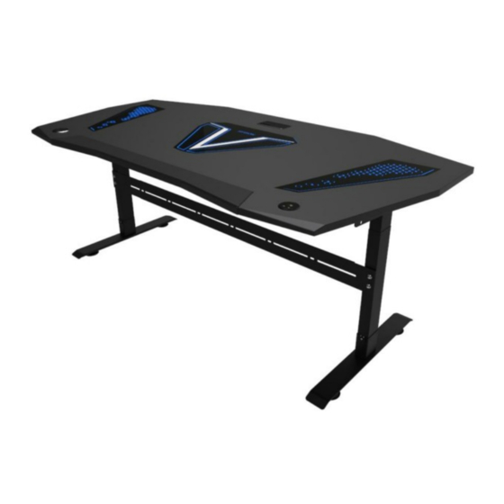
- Page 1 VADBL VALOR STATION Gamer workstation FOLLOW THE LINK FOR STEP BY STEP VIDEO ASSEMBLY MANUAL Please assemble your product on soft surface to avoid scratches and damages on lacquer.
- Page 2 The Desk You Deserve Thank you for making StudioDesk your desk of choice! Before beginning assembly of your stand, let s get familiar with the parts you have received in your package. Please match the corresponding numbers on this page with the drawings. Parts 1. Motorized Electric legs 2. Desk surface 3. Set of glasses 4. Cable management bar 1300 mm OPTIONAL PC THRONE OPTIONAL SHELVES POWER CORD CONTROLER Hardware Tools needed (Not included) M6 Screw Washers Plastic cover 7 pcs 15 pcs 2 pcs Self adhesive CUP Holder Cable holder 1 pc LED SET 5 pcs...
- Page 3 Step One Assemble the motorized legs as per included manual. Place desk surface to the floor and fix electric platform to using M6 screws as Shown on the illustration right. From the top use hexagon long screws as shown on the illustration. Step TWO Install Metal bridge with M6 screws. Step Three Fasten bridge with nuts and M6 screws.
- Page 4 Step Four Turn desk to standing position and Install controller and metal cap holder. Step Five LED Lights Please follow our step-by-step video assembly manual to connect led lights properly. Step Six Put glass carefully into the place. To control LED lights you’ll need app shown the video on the link above.
- Page 5 XTCL200 Electric In Height Adjustable Desk Frame ASSEMBLY MANUAL Electric In Height Adjustable Desk Frame 2 lifting column 2 stages Item No. XTCL200 Executive standard: GBT 33242008 <<Furniture general technical conditions>> GBT 33252008 <<Metal furniture general technical conditions>> EN 125212009 <<Furniture Strength, durability and safetyRequirements for domestic tables>> Follow me 1.First check contents to make sure nothing is missing.
- Page 6 A . Exploed view B. Part List 1. Adjustable foot 8.Power line 2. Bottom 9. Extendable rod 3. Height adjustable 10. Upper beam 4. Top support 11. M6×12 screw 32pc 5. Control Switch 12. ST4×16 screw 15pc 6. 6Core patch cord 13. Ribbon 7. Control box 14.
- Page 7 C. Assembly 1. Install the frame work on lifting columns with Allen key ( Pic 1 and Pic 2 ) 2. Install the top support with Allen key ( Pic 3 and Pic 4 ) 3. Install the bottom with Allen key ( Pic 5 and Pic 6 )
- Page 8 4. Install the extendable rod to the hole of frame and fix it with Allen key (Pic 7 and Pic 8 )
Need help?
Do you have a question about the VALOR and is the answer not in the manual?
Questions and answers