Table of Contents

Related Manuals for KLINGER CMF V Series


Summary of Contents for KLINGER CMF V Series
- Page 1 Klinger CMF Instruction Manual Page 1 Coriolis Massflowmeter Klinger CMF type V and U Instruction Manual KLINGER Denmark A/S | Nyager 12-14 | DK-2605 Brøndby | +45 43 64 66 11 | salesinstrumentation@klinger.dk | www.klinger.dk...
- Page 2 Prohibited matters, if not complying with, it may affect the use performance or safety performance of the instrument. KLINGER Denmark A/S | Nyager 12-14 | DK-2605 Brøndby | +45 43 64 66 11 | salesinstrumentation@klinger.dk | www.klinger.dk...
- Page 3 It is inconvenient to observe the display contents of the LCD panel. Please read this guide carefully before use. There is a risk of damage to the instrument. KLINGER Denmark A/S | Nyager 12-14 | DK-2605 Brøndby | +45 43 64 66 11 | salesinstrumentation@klinger.dk | www.klinger.dk...
-
Page 4: Table Of Contents
Software Operation Guide Page 27 Chapter VI Communication Page 48 Chapter VII Troubleshooting Page 61 Chapter VIII Daily Care and Maintenance Page 68 KLINGER Denmark A/S | Nyager 12-14 | DK-2605 Brøndby | +45 43 64 66 11 | salesinstrumentation@klinger.dk | www.klinger.dk... -
Page 5: Chapter I Introduction
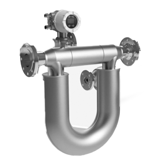
Figure 1-12 US series integral mass flowmeter, with T1, T2 and T3 transmitters Figure 1-13 US series remote mass flowmeter sensor, with T1, T2 and T3 transmitters KLINGER Denmark A/S | Nyager 12-14 | DK-2605 Brøndby | +45 43 64 66 11 | salesinstrumentation@klinger.dk | www.klinger.dk... - Page 6 Figure 1-18 VS series integral mass flowmeter Figure 1-19 VS series remote mass flowmeter sensor Figure 1-14 remote mass flowmeter transmitter KLINGER Denmark A/S | Nyager 12-14 | DK-2605 Brøndby | +45 43 64 66 11 | salesinstrumentation@klinger.dk | www.klinger.dk...
-
Page 7: Chapter Ii Installation
Ideal installation location will get the best product performance Consider the following criteria when choosing the location of the SCM 2.1.4.1.1 Away from sources of electromagnetic interference KLINGER Denmark A/S | Nyager 12-14 | DK-2605 Brøndby | +45 43 64 66 11 | salesinstrumentation@klinger.dk | www.klinger.dk... - Page 8 The transmitter should be placed such that the LCD is in a position and orientation that is easy to observe. 2.1.4.2.6 Maintainable There should be enough space for transmitter cover removing & wiring. 2.2 Installation KLINGER Denmark A/S | Nyager 12-14 | DK-2605 Brøndby | +45 43 64 66 11 | salesinstrumentation@klinger.dk | www.klinger.dk...
- Page 9 31-15/32 4-3/4 9-7/16 SCM-US-050N 24-1/2 21-3/8 31-15/32 4-3/4 9-7/16 SCM-US-050H 27-21/32 25-15/16 36-5/32 5-29/32 9-7/16 SCM-US-080N 30-1/16 26-11/16 37-7/16 5-29/32 9-7/16 KLINGER Denmark A/S | Nyager 12-14 | DK-2605 Brøndby | +45 43 64 66 11 | salesinstrumentation@klinger.dk | www.klinger.dk...
- Page 10 1760 1751 2150 2.2.1.3.2 Integral mass flowmeter with T1, T2 and T3 transmitters See table 2-16, 2-17 Figure 2-16 Figure 2-17 KLINGER Denmark A/S | Nyager 12-14 | DK-2605 Brøndby | +45 43 64 66 11 | salesinstrumentation@klinger.dk | www.klinger.dk...
- Page 11 SCM-US-100N 1045 SCM-US-100H 1064 1150 1490 SCM-US-150N 1160 1331 SCM-US-150H 1240 1257 1627 SCM-US-200N 1268 1257 1627 SCM-US-250N 1760 1751 2168 KLINGER Denmark A/S | Nyager 12-14 | DK-2605 Brøndby | +45 43 64 66 11 | salesinstrumentation@klinger.dk | www.klinger.dk...
- Page 12 51-11/16 9-21/32 3-15/16 SCM-US-150H 40-5/16 49-1/2 63-3/8 12-27/32 3-15/16 SCM-US-200N 49-15/16 49-1/2 64-15/16 12-27/32 3-15/16 SCM-US-250N 69-5/16 68-15/16 81-7/16 17-1/8 3-15/16 KLINGER Denmark A/S | Nyager 12-14 | DK-2605 Brøndby | +45 43 64 66 11 | salesinstrumentation@klinger.dk | www.klinger.dk...
- Page 13 2.2.1.3.4 Remote mass flowmeter with T1, T2 and T3 transmitters See figure 2-22, 2-23, 2-24, and 2-25 Figure 2-22 Figure 2-23 Figure 2-24 Figure 2-25 KLINGER Denmark A/S | Nyager 12-14 | DK-2605 Brøndby | +45 43 64 66 11 | salesinstrumentation@klinger.dk | www.klinger.dk...
- Page 14 2.2.1.3.4.2 Metric size, mm See table 2-16 Table 2-16 Specification Line Size SCM-US-001N SCM-US-002N SCM-US-005N SCM-US-010N SCM-US-015N SCM-US-025N SCM-US-040N SCM-US-040H SCM-US-050N SCM-US-050H SCM-US-080N KLINGER Denmark A/S | Nyager 12-14 | DK-2605 Brøndby | +45 43 64 66 11 | salesinstrumentation@klinger.dk | www.klinger.dk...
- Page 15 6-5/8 7-9/16 2.2.1.4.1.2 Metric size, mm See table 2-18 Table 2-18 Specification Line Size SCM-VS-005 SCM-VS-015 SCM-VS-025 SCM-VS-040 SCM-VS-050 SCM-VS-080 1336 KLINGER Denmark A/S | Nyager 12-14 | DK-2605 Brøndby | +45 43 64 66 11 | salesinstrumentation@klinger.dk | www.klinger.dk...
- Page 16 6-5/8 4-5/8 2.2.1.4.2.2 Metric size, mm See table 2-20 Table 2-20 Specification Line Size SCM-VS-005 SCM-VS-015 SCM-VS-025 SCM-VS-040 SCM-VS-050 SCM-VS-080 1336 KLINGER Denmark A/S | Nyager 12-14 | DK-2605 Brøndby | +45 43 64 66 11 | salesinstrumentation@klinger.dk | www.klinger.dk...
- Page 17 Inverted installation prevents higher density media from accumulating in the sensor tubes. KLINGER Denmark A/S | Nyager 12-14 | DK-2605 Brøndby | +45 43 64 66 11 | salesinstrumentation@klinger.dk | www.klinger.dk...
- Page 18 2.2.2.2.1 Normal line size: DN10~DN250(Figure 2-37) Pipe support point Figure 2-37 2.2.2.2.2 Small line size:DN1~DN5(Figure 2-38, 2-39, 2-40, 2-41) Figure 2-38 Figure 2-39 KLINGER Denmark A/S | Nyager 12-14 | DK-2605 Brøndby | +45 43 64 66 11 | salesinstrumentation@klinger.dk | www.klinger.dk...
- Page 19 2.2.2.3.5.2 The sensor should be removed prior to the welding operations on the pipe. 2.2.2.3.5.3 Note the default forward flow direction indicated on the sensor housing. KLINGER Denmark A/S | Nyager 12-14 | DK-2605 Brøndby | +45 43 64 66 11 | salesinstrumentation@klinger.dk | www.klinger.dk...
- Page 20 2.2.3.2.2 Ensure that the cover of transmitter is fully tightened. 2.2.3.2.3 Ensure that the O-ring is firmly seated and in good condition. KLINGER Denmark A/S | Nyager 12-14 | DK-2605 Brøndby | +45 43 64 66 11 | salesinstrumentation@klinger.dk | www.klinger.dk...
-
Page 21: Chapter Iii Wiring
3.1.3.1 The transmitter’s terminal layout is detailed in figure3-2, and the terminal functions are defined by figure 3-3. ( Analog Loop 2 is not default option) KLINGER Denmark A/S | Nyager 12-14 | DK-2605 Brøndby | +45 43 64 66 11 | salesinstrumentation@klinger.dk | www.klinger.dk... - Page 22 Use only Walsn provided 9-wire cable (illustrated in figure 3-4) to connect the sensor to the transmitter. Figure 3-4 remote cable profile KLINGER Denmark A/S | Nyager 12-14 | DK-2605 Brøndby | +45 43 64 66 11 | salesinstrumentation@klinger.dk | www.klinger.dk...
- Page 23 3-6, and the terminal functions are defined by Table 3-3 Figure 3-6 Remote conjunction box of T1, T2 and T3 version transmitter KLINGER Denmark A/S | Nyager 12-14 | DK-2605 Brøndby | +45 43 64 66 11 | salesinstrumentation@klinger.dk | www.klinger.dk...
- Page 24 The ground wire should be as short as possible, and the grounding resistance should be less than 4 Ω. 3.4.6 Draining point All wiring should be set up draining point. KLINGER Denmark A/S | Nyager 12-14 | DK-2605 Brøndby | +45 43 64 66 11 | salesinstrumentation@klinger.dk | www.klinger.dk...
-
Page 25: Chapter Iv Initial Start-Up
4.2.2.3 Close the nearest shutoff valve in the upstream of the flow meter. 4.2.2.4 Initiate the zero calibration using the transmitter’s user interface (Figure 4-1) KLINGER Denmark A/S | Nyager 12-14 | DK-2605 Brøndby | +45 43 64 66 11 | salesinstrumentation@klinger.dk | www.klinger.dk... - Page 26 4.2.3.3 Zero point instability may indicate problems with the mechanical installation of the flowmeter (e.g. vibration interference) KLINGER Denmark A/S | Nyager 12-14 | DK-2605 Brøndby | +45 43 64 66 11 | salesinstrumentation@klinger.dk | www.klinger.dk...
-
Page 27: Software Operation Guide
Touching the glass in front of key just like figure 5-2, the red indicator aside will light if operation is ok. KLINGER Denmark A/S | Nyager 12-14 | DK-2605 Brøndby | +45 43 64 66 11 | salesinstrumentation@klinger.dk | www.klinger.dk... - Page 28 The transmitter operation panel is equipped with a LCD display with a resolution of 128 * 64, which is used to display the state parameters and configuration parameters. 5.2 Menu 5.2.1 Menu tree KLINGER Denmark A/S | Nyager 12-14 | DK-2605 Brøndby | +45 43 64 66 11 | salesinstrumentation@klinger.dk | www.klinger.dk...
- Page 29 Klinger CMF Instruction Manual Page 29 KLINGER Denmark A/S | Nyager 12-14 | DK-2605 Brøndby | +45 43 64 66 11 | salesinstrumentation@klinger.dk | www.klinger.dk...
- Page 30 Klinger CMF Instruction Manual Page 30 KLINGER Denmark A/S | Nyager 12-14 | DK-2605 Brøndby | +45 43 64 66 11 | salesinstrumentation@klinger.dk | www.klinger.dk...
- Page 31 Klinger CMF Instruction Manual Page 31 KLINGER Denmark A/S | Nyager 12-14 | DK-2605 Brøndby | +45 43 64 66 11 | salesinstrumentation@klinger.dk | www.klinger.dk...
- Page 32 Klinger CMF Instruction Manual Page 32 KLINGER Denmark A/S | Nyager 12-14 | DK-2605 Brøndby | +45 43 64 66 11 | salesinstrumentation@klinger.dk | www.klinger.dk...
- Page 33 Klinger CMF Instruction Manual Page 33 KLINGER Denmark A/S | Nyager 12-14 | DK-2605 Brøndby | +45 43 64 66 11 | salesinstrumentation@klinger.dk | www.klinger.dk...
- Page 34 Klinger CMF Instruction Manual Page 34 KLINGER Denmark A/S | Nyager 12-14 | DK-2605 Brøndby | +45 43 64 66 11 | salesinstrumentation@klinger.dk | www.klinger.dk...
- Page 35 The LCD will back the Main Screen automatically while all touch keys keep locking 5 minutes without any operation. KLINGER Denmark A/S | Nyager 12-14 | DK-2605 Brøndby | +45 43 64 66 11 | salesinstrumentation@klinger.dk | www.klinger.dk...
- Page 36 : The primary and secondary display overflow. Please change the display variable unit. ■: Tube process frequency is far from empty pipe frequency over 40%. KLINGER Denmark A/S | Nyager 12-14 | DK-2605 Brøndby | +45 43 64 66 11 | salesinstrumentation@klinger.dk | www.klinger.dk...
- Page 37 Perform the zero calibration procedure (See section 4.1.2) 5.2.5.3.3 MAIN DISP Configure the measured variable & unit (see table 5-1) displayed in primary display. 5.2.5.3.4 SUB DISP KLINGER Denmark A/S | Nyager 12-14 | DK-2605 Brøndby | +45 43 64 66 11 | salesinstrumentation@klinger.dk | www.klinger.dk...
- Page 38 5.2.5.3.10 FIXED DENS 5.2.5.3.10.1 When the input value is “0”, the displayed density is the measured value, “volume KLINGER Denmark A/S | Nyager 12-14 | DK-2605 Brøndby | +45 43 64 66 11 | salesinstrumentation@klinger.dk | www.klinger.dk...
- Page 39 5.2.5.3.18.5 While”4~20mA #2” is configured”M1/M”or”V1/V”, “MINVAL OUT2#” should be 0% and the value & unit will be no avail. 5.2.5.3.19 MAX OUT FREQ KLINGER Denmark A/S | Nyager 12-14 | DK-2605 Brøndby | +45 43 64 66 11 | salesinstrumentation@klinger.dk | www.klinger.dk...
- Page 40 5.2.5.3.28.2.4 REV: Identical to “forward” but positive flow is defined as opposite the default flow direction. See table 5-2. 5.2.5.3.28.3 Recommended settings KLINGER Denmark A/S | Nyager 12-14 | DK-2605 Brøndby | +45 43 64 66 11 | salesinstrumentation@klinger.dk | www.klinger.dk...
- Page 41 5.2.5.3.30.3 T/DA/DB: input Temperature,Density(A) & Density(B) for each point. 5.2.5.3.30.4 Temperature input range:-50℃~300℃ 5.2.5.3.30.5 Density input range:0g/cm3~3 g/cm3 5.2.5.3.31 RESET MEMORY Restore the configuration to the factory default. KLINGER Denmark A/S | Nyager 12-14 | DK-2605 Brøndby | +45 43 64 66 11 | salesinstrumentation@klinger.dk | www.klinger.dk...
- Page 42 + 1 ) Definition: Q : Flow after Compensation Q: Flow before Compensation : Temperature correction coefficient T: Process temperature : Calibration temperature KLINGER Denmark A/S | Nyager 12-14 | DK-2605 Brøndby | +45 43 64 66 11 | salesinstrumentation@klinger.dk | www.klinger.dk...
- Page 43 5.2.6.3.16.1 Record the temperature while density calibration, which is used for compensating density measurement deviation caused by process temperature changing. 5.2.6.3.16.2 Matters needing attention KLINGER Denmark A/S | Nyager 12-14 | DK-2605 Brøndby | +45 43 64 66 11 | salesinstrumentation@klinger.dk | www.klinger.dk...
- Page 44 Set sensor nonlinear correction point 5. 5.2.6.3.25 SET LOOP V 5.2.6.3.25.1 Setting the voltage amplitude of the sensor pick up coil & low alarm level. KLINGER Denmark A/S | Nyager 12-14 | DK-2605 Brøndby | +45 43 64 66 11 | salesinstrumentation@klinger.dk | www.klinger.dk...
- Page 45 The CoT has been set by the factory, non annual inspection or professional personnel do not operate. 5.2.6.3.32 CoS 5.2.6.3.32.1 The adopted filter coefficient when flow change slope<Grd2, and phase difference <DoS. KLINGER Denmark A/S | Nyager 12-14 | DK-2605 Brøndby | +45 43 64 66 11 | salesinstrumentation@klinger.dk | www.klinger.dk...
- Page 46 Displaying the serial number of sensor used. 5.2.7.4.4 FIRMWARE Displaying the version of software used. 5.2.7.4.5 M. FLOW kg/h Display the lower and upper mass range value. KLINGER Denmark A/S | Nyager 12-14 | DK-2605 Brøndby | +45 43 64 66 11 | salesinstrumentation@klinger.dk | www.klinger.dk...
- Page 47 5.2.8.3.3.2 A total of 5 test points: 0%, 25%, 50%, 75% & 100%. 5.2.8.3.4 CLR ERROR Clear ERROR alarm code. 5.2.8.3.5 REBOOT Reset the flow meter with power on. KLINGER Denmark A/S | Nyager 12-14 | DK-2605 Brøndby | +45 43 64 66 11 | salesinstrumentation@klinger.dk | www.klinger.dk...
-
Page 48: Chapter Vi Communication
6.1.2.5 The warning information about the device description or device status may be ignored in the connection process. KLINGER Denmark A/S | Nyager 12-14 | DK-2605 Brøndby | +45 43 64 66 11 | salesinstrumentation@klinger.dk | www.klinger.dk... - Page 49 Process temp Dens Snsr Freq Phas Diff Strd Zero RealT Zero LMS Ampl RMS Ampl Figure 6-4 Process variables 6.1.3.3 Diag/Service KLINGER Denmark A/S | Nyager 12-14 | DK-2605 Brøndby | +45 43 64 66 11 | salesinstrumentation@klinger.dk | www.klinger.dk...
- Page 50 Trnsmt Hw Ver Final assmbly num Trnsmt SN. Revision #`s Sensor SN. Device ID Information Figure 6-6 Basic setup 6.1.3.5 Detailed setup KLINGER Denmark A/S | Nyager 12-14 | DK-2605 Brøndby | +45 43 64 66 11 | salesinstrumentation@klinger.dk | www.klinger.dk...
- Page 51 Grd1C para Grd2 para Grd2C para CoT para CoS para DoS para ATH para DoF Figure 6-7 detailed setups 6.1.3.6 Review KLINGER Denmark A/S | Nyager 12-14 | DK-2605 Brøndby | +45 43 64 66 11 | salesinstrumentation@klinger.dk | www.klinger.dk...
- Page 52 Instrument address+ function code 0x10+ initial address register (2 bytes, the high-order byte in front) + register read and write number 2*N (2 bytes, the KLINGER Denmark A/S | Nyager 12-14 | DK-2605 Brøndby | +45 43 64 66 11 | salesinstrumentation@klinger.dk | www.klinger.dk...
- Page 53 Zero point calibration Read back to 1 Write 0 Read and Write 1076 Refresh damping 0~60.0s /0.5 1078 Decimal digits Read and Write KLINGER Denmark A/S | Nyager 12-14 | DK-2605 Brøndby | +45 43 64 66 11 | salesinstrumentation@klinger.dk | www.klinger.dk...
- Page 54 With the process variable 1130 current output Read Only unit unit-CH1 Configuration of With the process variable 1132 Read Only current output unit KLINGER Denmark A/S | Nyager 12-14 | DK-2605 Brøndby | +45 43 64 66 11 | salesinstrumentation@klinger.dk | www.klinger.dk...
- Page 55 /20.0 Calibrated Read and Write 1182 Temperature 0~5.000 /1.0 coefficient T1 Calibrated Read and Write 1184 Temperature 0~5.000 coefficient T2 KLINGER Denmark A/S | Nyager 12-14 | DK-2605 Brøndby | +45 43 64 66 11 | salesinstrumentation@klinger.dk | www.klinger.dk...
- Page 56 Write Only 1236 Comm password 0~9999 /5124 1238 Comm password reset 0~9999 Write Only Double component Read and Write 1240 calculation KLINGER Denmark A/S | Nyager 12-14 | DK-2605 Brøndby | +45 43 64 66 11 | salesinstrumentation@klinger.dk | www.klinger.dk...
- Page 57 6.2.3.2 Volumetric flow unit The codes for the various volumetric flow rates units are defined in table 6-3. KLINGER Denmark A/S | Nyager 12-14 | DK-2605 Brøndby | +45 43 64 66 11 | salesinstrumentation@klinger.dk | www.klinger.dk...
- Page 58 6.2.3.9 Mass flow range unit The codes for mass range units are defined in table 6-10. Table 6-10 mass range unit Code KLINGER Denmark A/S | Nyager 12-14 | DK-2605 Brøndby | +45 43 64 66 11 | salesinstrumentation@klinger.dk | www.klinger.dk...
- Page 59 CH2 fixed CH1 and CH2 fixed 6.2.3.17 Error code The codes used for troubleshooting the flow meter are defined in table 6-18. KLINGER Denmark A/S | Nyager 12-14 | DK-2605 Brøndby | +45 43 64 66 11 | salesinstrumentation@klinger.dk | www.klinger.dk...
- Page 60 0, then the corresponding current loop output will return to outputting the assigned process variable. KLINGER Denmark A/S | Nyager 12-14 | DK-2605 Brøndby | +45 43 64 66 11 | salesinstrumentation@klinger.dk | www.klinger.dk...
-
Page 61: Chapter Vii Troubleshooting
7.4.1 Flow meter does not run The typical causes of, and solutions to, this problem are laid out in table 8-2. KLINGER Denmark A/S | Nyager 12-14 | DK-2605 Brøndby | +45 43 64 66 11 | salesinstrumentation@klinger.dk | www.klinger.dk... - Page 62 Wrong flow unit or low flow Ensure valves are properly cutoff value seated Mounting forces on flow Purge flow tube meter Ensure flowmeter is isolated KLINGER Denmark A/S | Nyager 12-14 | DK-2605 Brøndby | +45 43 64 66 11 | salesinstrumentation@klinger.dk | www.klinger.dk...
- Page 63 Ensure slug flow does not problem appear Filter coefficient is too large Ensure sensor is oriented as recommended Adjust small filter coefficient KLINGER Denmark A/S | Nyager 12-14 | DK-2605 Brøndby | +45 43 64 66 11 | salesinstrumentation@klinger.dk | www.klinger.dk...
- Page 64 (even other characteristic parameters flowmeters) changed Change the installation location Density output Density coefficient error Verify that all parameters match the KLINGER Denmark A/S | Nyager 12-14 | DK-2605 Brøndby | +45 43 64 66 11 | salesinstrumentation@klinger.dk | www.klinger.dk...
- Page 65 Flow over range, density over Try again Zero calibration 3000g/cm3. Replace Flow meter with larger line Exceed the lower limit: The size. KLINGER Denmark A/S | Nyager 12-14 | DK-2605 Brøndby | +45 43 64 66 11 | salesinstrumentation@klinger.dk | www.klinger.dk...
- Page 66 7.5.1.8 Please check the voltage of the transmitter power supply terminal, which should be in the specified range. 7.5.2 Check the wiring between the sensor and the transmitter. KLINGER Denmark A/S | Nyager 12-14 | DK-2605 Brøndby | +45 43 64 66 11 | salesinstrumentation@klinger.dk | www.klinger.dk...
- Page 67 7.5.5.2 Test the resistance between Pin3/Pin4 (L+/GND) & Pin5/Pin4(R+/GND). The value difference should be less than ±2Ω. 7.5.5.3 Test the resistance between Pin1/Pin2 (D+/D-). Short or open means faulty coil. KLINGER Denmark A/S | Nyager 12-14 | DK-2605 Brøndby | +45 43 64 66 11 | salesinstrumentation@klinger.dk | www.klinger.dk...
-
Page 68: Chapter Viii Daily Care And Maintenance
Please do not disassemble or Comprehensive At least once Please contact the manufacturer clean the flow meter inspection in 5 years voluntarily KLINGER Denmark A/S | Nyager 12-14 | DK-2605 Brøndby | +45 43 64 66 11 | salesinstrumentation@klinger.dk | www.klinger.dk... - Page 69 8.3.2.2 Damage caused by fire, flood, abnormal voltage, vibration, etc.. 8.3.2.3 Damage caused by the flow meter used in non normal function. 8.3.2.4 Man-made damage. KLINGER Denmark A/S | Nyager 12-14 | DK-2605 Brøndby | +45 43 64 66 11 | salesinstrumentation@klinger.dk | www.klinger.dk...
- Page 70 Klinger CMF Instruction Manual Page 70 KLINGER Danmark A/S Nyager 12-14 DK-2605 Broendby Denmark Phone +45 4364 6611 www.klinger.dk KlingerCMF manual 0421.pdf KLINGER Denmark A/S | Nyager 12-14 | DK-2605 Brøndby | +45 43 64 66 11 | salesinstrumentation@klinger.dk | www.klinger.dk...
Need help?
Do you have a question about the CMF V Series and is the answer not in the manual?
Questions and answers