Table of Contents
Advertisement
Quick Links
Advertisement
Table of Contents

Related Manuals for AquaLabo Supratec S200 WCS


Summary of Contents for AquaLabo Supratec S200 WCS
- Page 1 S200 WCS User Manual User Manual S200 WCS Update August 2021...
- Page 2 AQUALABO Registered office: AQUALABO - 90 rue du Professeur Paul MILLIEZ - 94500 CHAMPIGNY SUR MARNE – FRANCE PLC with capital of 1,492,900 Euros – SIRET (Business registration number) 499 665 230 00011- RCS (Trade & Corporate Register) Créteil – NAF (Business subsector ID number) 2651B - Intra-Community VAT: FR 91 499665230 www.aqualabo.fr Hotline: +33...
-
Page 3: Table Of Contents
Contents 1 General information ......................... 6 1.1 General overview ......................6 1.2 Notes in bold print ......................6 1.3 Warranty ........................... 6 1.4 Electrical connection ......................7 1.5 Safety Instructions ......................7 1.6 Damage due to transport ....................7 2 Technical data ......................... 8 2.1 General overview ...................... - Page 4 6.6 Calibration chlorine/chlorine dioxide/ozone (valve...) ............25 6.6.1 Calibration process when using comparison measurement ........26 6.6.2 Automatic cleaning of the chlorine/chlorine dioxide/ozone probe ......27 6.7 Controller settings ......................27 6.7.1 Set point settings ...................... 28 6.7.2 Proportional band (P-share) ..................28 6.7.3 Integral action time (Integral gain) ................
- Page 5 7.2.3 Direction of control action ..................35 7.2.4 Assignment of the control output ................35 7.2.5 Pulse frequency ......................35 7.2.6 Pulse interval control ....................36 7.2.7 Minimum pulse ......................36 7.2.8 Setting of control parameters ..................36 7.2.9 Calibration of probes ....................37 8 Maintenance and servicing ....................
-
Page 6: General Information
1 General information 1.1 General overview This technical manual contains instructions for installing, commissioning, maintaining and repairing the S200 WCS measurement and monitoring device. Please follow the safety instructions and notes in bold print at all times! 1.2 Notes in bold print Titles in bold print, alerts and warnings have the following meaning, in this technical manual: Important:... -
Page 7: Electrical Connection
1.4 Electrical connection Warning: Only use the power supply specified on the nameplate to run the S200 measurement and monitoring device! The device is delivered to run, by default, on a 230V/50Hz or 110V/50Hz power supply. 1.5 Safety Instructions S200 WCS measuring and monitoring devices are manufactured and tested according to standards DIN EN 61010-1 / VDE 0411-1. -
Page 8: Technical Data
2 Technical data 2.1 General overview Article Adjustment ranges Power supply unit 230 V/AC ± 10 % (50/60Hz) 117 V/AC ± 10 % (50/60Hz) Power consumption 16 VA Level of protection IP 65 Fuse (device) 80 mAT (230V) 160 mAT (117V) Electrical properties of the contact relay Max. -
Page 9: Variable Measurements
2.2 Variable measurements Measured Measurement and control Resolution variable range 0.01 mV/input resistance >5x10¹¹ Ω -2.00 pH ... 16.00 pH 1 mV/input resistance >1x10⁶ Ω Redox -1500 mV ...+1500 mV Temperature -30 °C...+140 °C 0.1 °C / PT100/ Pt1000 switchable 0.01 mA / 50 Ω... -
Page 10: Description
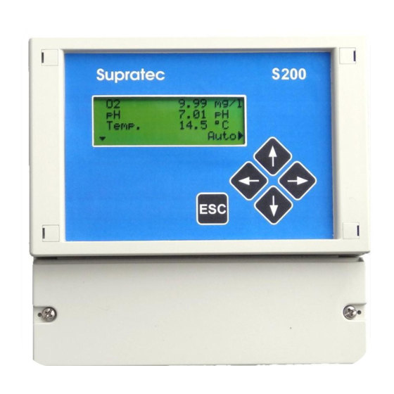
3 Description The S200 WCS measuring and monitoring device is easy to use. Equipment: • Backlit display • Cursor-controlled operation with only 5 keys • Browser menu in plain text • Up to 6 different settings simultaneously (depending on the type of code) •... - Page 11 pH sensor: special pH glass and reference Metal measuring electrode (gold) and reference. Pt1000 Temperature sensor Measuring chamber Counter electrode pH glass/measure Counter electrode Flow Metal measuring electrode pH reference Temperature Pt1000 Reference jumper User Manual S200 WCS Update August 2021...
-
Page 12: Operation
4 Operation 4.1 Controls Display Backlit LCD screen with 4 lines of 20 characters each Cursor control/Numerical value increase Choice confirmation/Function change Cursor control/Numerical value decrease Choice of operating menu Value backup/Return to level 1 menu Cancel input without saving/Return to the home screen. User Manual S200 WCS Update August 2021... -
Page 13: Display
4.2 Display 4. 2. 1 G r aph ic s y mbo l 4. 2. 1 .1 Ma i n s c re e n for v is u a l i z at i on of m e as ur e m en t s a n d r e la t ed u n its : 7.89 mg/l 7.82... -
Page 14: General Menu
Note: In the instructions for use, the following line appears above the menu window, as follows: /Service/LCD Display/ This line enables users to easily find this menu item in the device. /Service/LCD Display/: This means that the selected sub-menu is "Service”. /Service/LCD Display/: This means that an additional sub-menu has been selected. -
Page 15: Example Of Access To A Sub-Menu, Selection Of "Temperature Compensation" Menu15
4. 2. 3 E xa mpl e of ac c es s t o a sub - me nu, s el ect io n of "T emp e r at u re Co mpe ns at ion” men u Calibration Temp. - Page 16 ↕ A flashing arrow indicates you are in input mode. Use the arrow keys - up or down - to change the numeric value. ← This indicates that the cursor key - left arrow - is used to complete the input and the value is saved.
-
Page 17: Installation
5 Installation WARNING Potential risk of electrocution: Always shut off power to the equipment when connecting it. The lower part of the housing, protective cover of the housing may only be removed after switching off the device. CAUTION Potential damage to the device: The internal electronic components of the device may be damaged by static electricity which in turn may adversely affect its performance and function. - Page 18 Digital output 2 72+73 Digital output for electronic monitoring Max. load 200 mA / 30V Dosing pumps Switching from output relay 1 80+81 Potential-free contact Switching from output relay 2 82+83 Potential-free contact Switching from output relay 3 84+85 Potential-free contact Union Terminals Description...
-
Page 19: Access And Display
6 Access and display 6.1 How to use menus All settings are accessible via a menu. Changing a defined value (for example). Note: This manual includes all available menu items. Depending on the selected code (see the specific “Codes” paragraph), all menu items cannot be displayed, and/or, all menu items cannot be selected. -
Page 20: Adjusting The Backlight
6. 2. 2 Adju st ing t h e b a c kli g ht The intensity of the backlight can be changed using the "backlight” menu. Note: Backlight intensity: it should be as bright as required. A backlight that is too bright reduces the useful life of the display. -
Page 21: Ph Sensor Calibration
6.4 pH sensor calibration Terminal assignment Wire Function Connection Shielding Reference electrode Terminal 1 Inner conductor pH- electrode Terminal 2 Reference of pH electrode: 202101SU /Calibration/Calibration pH/ Note: The pH probe must be checked periodically. A buffer solution is used for this. If there are deviations exceeding 0.2 pH, a calibration of the pH probe should be carried out. -
Page 22: Calibration Process With Buffer Solution For Ph Probe
6. 4. 1 Ca lib r at i on pr oc e ss w it h buff e r sol ut i on f or pH p rob e Buffer solutions, such as pH 4. and pH 7, must be ready for the calibration. 1. -
Page 23: Calibration Redox (Redox)
6. 4. 1 .1 In ter ro g at i ng t h e s l op e /z er o p o in t of t h e p H p r ob e The current slope and zero point deviation of the pH probe are displayed in the calibration menu. -
Page 24: Calibration Process With Buffer Solution For Redox Probe
/Calibration/Calibration ORP/ Note: The Redox (ORP) probe must be checked periodically. A buffer solution is used for this, e.g. 475 mV. If there are deviations exceeding +/- 10mV, a calibration of the Redox probe should be carried out. This calibration is a one point calibration. To do this you need a Redox buffer solution. As standard, 475 mV has proven, for example. -
Page 25: Calibration Chlorine/Chlorine Dioxide/Ozone (Valve
6. 5. 1 .2 Ex pl a n at i on z er o p o i nt R ed ox pr o be Physically, the zero point of a new Redox probe is 0 mV. This value can vary by +/- 25mV. During operation, the zero point changes in a positive or negative direction. -
Page 26: Calibration Process When Using Comparison Measurement
A deviation of the measuring value is possible after an automatic probe cleaning process, since the probe has been newly polarized, which can result in a temporarily higher measuring value. If a calibration of pH or redox value is required, this calibration should be carried out first. -
Page 27: Automatic Cleaning Of The Chlorine/Chlorine Dioxide/Ozone Probe
6. 6. 2 Aut o mat ic cl ea nin g o f t h e chl or in e/ ch lo ri n e d io xi de /oz on e p rob e /Basic setting/POT cleaning Note: When set to 0, the cleaning feature is deactivated. A maximum 4 cleaning processes can be carried out per day. -
Page 28: Set Point Settings
6. 7. 1 S et p oint set t ing s You can set the desired set point for the selected measurement in this menu. Set the desired value, e.g. 7.30 pH. 6. 7. 2 P ropo rt ion al b and ( P - sh ar e) Note: If a proportional band of 0.00 pH is set, the controller works as On-Off controller/controller without proportional action. -
Page 29: Manual Operation Mode
6.8 Manual operation mode 6. 8. 1 Manual contr o lle r m ode /Manual mode/ The controlled variables of the controller can be set in the manual controller settings. This setting can be made for each controller separately. The output signal provided for the controller is controlled directly, e.g. -
Page 30: Temperature Compensation
6.10 Temperature compensation In case of different measurements, the measuring signal is dependent on the temperature. The S200 measurement and control device compensates the measured values to a reference temperature of 25°C. The temperature compensation takes place automatically if a temperature sensor is used and the automatic mode for the temperature compensation is enabled. -
Page 31: Current Range 0/4Ma
6. 1 1. 2 Cur ren t r an ge 0/4mA /Basic settings/Analog outputs/Analog output 1 A current range 0-20 mA or 4-20 mA is to be set. 6. 1 1. 3 Set ting th e ra n ge /Basic settings/Analog outputs/Analog output 1 Set the beginning (0/4 mA) and end (20mA) of the analog output range. -
Page 32: Device Data
6. 1 3. 1 Device d ata You can retrieve specific data in the menu “Device data”, for example the serial number, the software version and the date of manufacture. 6. 1 3. 2 Ana log inputs The function of the analog inputs can be checked here. 6. -
Page 33: Initial Commissioning
7 Initial commissioning 7.1 Checking the hardware installation Warning: Before connecting the supply voltage to the device, check the supply voltage against the data on the rating plate and compare these. Check the wiring of the device against the wiring diagram. 7.2 Basic device settings After switching on, select the function “Enter code”. -
Page 34: Controller Reading Assignment
Assign the required reading to parameter 1, e.g. pH measurement or temperature. Use the key to select the desired reading assignment. /Basic settings/Select parameter/Parameter 1/ If a parameter is not to be used, select “No measurement”. /Basic settings/Select parameter/Parameter 1/ According to the number of selected parameters, what is indicated in the display will be different, for example two parameters (pH and temperature). -
Page 35: Direction Of Control Action
/Basic settings/Control param./Setting control.1/ Use the key to select the desired measuring value allocation. If a parameter is not used, select the reading assignment “No measurement”.. For additional control settings, see chapter “Controller settings". 7. 2. 3 Di re ct ion of co nt rol a ct i on Basic settings/Control param./Setting control.1/ The direction of the controller action is be determined with the setting “Control direction”. -
Page 36: Pulse Interval Control
The controller output is switched to pulse frequency via the pulse frequency setting. A setting of 0 p/h switches the controller to pulse interval controller. The numerical value, e.g. 36 p/h, means that 3600 pulses/hour are released at 100% dosing capacity. 7. -
Page 37: Calibration Of Probes
/Controller setting/Setting control.1/ The complete setting of the controller is described in the chapter “Controller settings". 7. 2. 9 Calib ration of p ro be s Finally, the connected probes are to be calibrated according to the calibration instructions. Please continue reading under section (6.4). User manual S200 WCS Update August 2021... -
Page 38: Maintenance And Servicing
8 Maintenance and servicing The housing may only be wiped with a damp cloth; the use of sharp, caustic or abrasive cleaning agents (acid cleaners, lyes, etc.) is not permitted! The S200 measuring and control device is easy to maintain, but should be checked and serviced by a trained technician at regular intervals. -
Page 39: Alarm Messages
9 Alarm messages 9.1 List of error messages Alarm message Cause Activity Remedy Slope of pH probe pH measurement Controller function remains Recalibrate or replace active, faulty calibration the probe Slope of probe value is accepted < 50mV Error zero point pH pH measurement Controller function remains Recalibrate or replace... -
Page 40: Modbus Rtu
10 MODBUS RTU The S200 measuring and control device is equipped with a Modbus RTU interface. The hardware is a RS 485 interface. Shielding = terminal 97 A = + Terminal 96 B = - Terminal 95 10.1 Shielding The use of shielded cables offers a high protection against electromagnetic interference, especially against high frequencies. -
Page 41: Sensor - Actuator Bus (Modbus Rtu)
11 Sensor – Actuator Bus (MODBUS RTU) The S200 measuring and control device is equipped with a sensor - actuator bus. The MODBUS RTU protocol is used. The hardware is a RS 485 interface. Shielding = terminal 94 A = + terminal 93 B = - terminal 92 +12V = terminal 91 0V = terminal 90... -
Page 42: Annex
12 Annex 12.1 What to do in case of a power failure In case of a power failure, the unit maintains the last operating state. Once the power is restored, the device continues to work with all previous settings. 12.2 Battery The S200 measuring and control device has a battery so that the internal clock keeps running if no voltage is connected. -
Page 43: Electrical Connection
13 Electrical connection Terminal Function Power input (see nameplate) Warning: The voltage specified on the nameplate must be observed. Terminal block PE Measuring input 1, e.g. measurement pH Measuring input 2, e.g. measurement redox or 0/4-20 mA with internal jumper Connection temperature sensor Pt 100 or Pt 1000 Connection extension module Please refer to the module description for details about the... -
Page 44: Hotline-Aftersales Service Contact Details
14 Hotline-Aftersales Service contact details AQUALABO ZA de Bellevue 115 Rue Michel Marion 56850 CAUDAN FRANCE Hotline: +33 (0) 4.11.71.97.41...
Need help?
Do you have a question about the Supratec S200 WCS and is the answer not in the manual?
Questions and answers