Table of Contents
Advertisement
Quick Links
Advertisement
Table of Contents

Subscribe to Our Youtube Channel
Related Manuals for iSystem IOM6 CAN/LIN


Summary of Contents for iSystem IOM6 CAN/LIN
- Page 1 IOM6 CAN/LIN V2.6 User Manual...
- Page 2 This document and all documents accompanying it are copyrighted by iSYSTEM AG and all rights are reserved. Duplication of these documents is allowed for personal use. In all other cases, written consent from iSYSTEM is required. iSYSTEM AG. All rights reserved.
-
Page 3: Table Of Contents
Important safety notice ......................... 5 Package content ............................6 Specifications ............................7 Operation ..............................8 Connecting the IOM6 CAN/LIN to the iC5700 ............................... 10 CAN message injection ......................................11 Cables & Adapters ......................................... 12 CAN cable DB9 ..........................................13 CAN cable banana jacks & pin wires ................................. 14 CAN BUS T adapter ........................................ -
Page 4: Iom6 Can/Lin
More information isystem.com/sdk. iSYSTEM's solutions run under the Microsoft® Windows® operating system or optionally within the Eclipse environment through a plug-in. All our software can be downloaded from the Downloads page at http://www.isystem.com. -
Page 5: Important Safety Notice
Do not operate the device outside its rated supply voltage or environmental range - Consult with iSYSTEM before using equipment outside of the parameters provided in this manual. This symbol is used within the manual to highlight further safety notices. -
Page 6: Package Content
Package content The standard IOM6 CAN/LIN order is delivered with the following components: IOM6 CAN/LIN 1m FNet Cable Grounding wire Ordering code: Ordering code: Ordering code: IC57040 BB-FNET-100 BB-WIRE User Manual... -
Page 7: Specifications
Specifications GENERAL Supply voltage 10°C to 40°C Storage temperature -10°C to 60°C Humidity 5% to 80% RH MECHANICAL Size 100 x 125 x 55 mm Weight ca. 440 g (without cables) ELECTRICAL Supply voltage Powered through the FNet CAN Channels 2 x Microchip MCP2562FD (galvanic isolation) DAP_RESET 2 x NXP TJA1027 (galvanic isolation) -
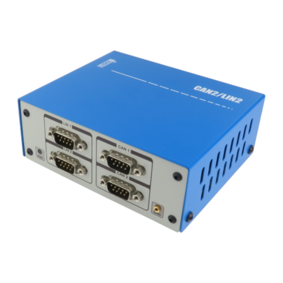
Page 8: Operation
Operation Device overview Device description The front face of the features: A – The indicator light provides the status of the hardware - At power on the LED will blink 5 times with a frequency of 1Hz, then it will stay ON continuously. If LED remains blinking or it doesn't blink on after power ON, please contact support. - Page 9 E – The FNet Port Although it looks similar to the HDMI interface, the FNet Port is not compatible with HDMI or any HDMI accessories. Connecting iSYSTEM hardware to the HDMI devices will damage the hardware and will render the iSYSTEM hardware warranty void.
-
Page 10: Connecting The Iom6 Can/Lin To The Ic5700
Connecting the IOM6 CAN/LIN to the iC5700 1. Make sure that the iC5700 BlueBox is powered off. 2. Connect the iC5700 FNet port to the FNet port of the IOM6 CAN/LIN Accessory using the supplied, certified, iSYSTEM FNet cable. IOM6 CAN/LIN Accessory winIDEA configuration and usage is described in the winIDEA Help. -
Page 11: Can Message Injection
CAN message injection CAN message injection is physically disabled by default. To enable injection remove the cover on your powered-down AOM CAN/LIN device and place jumpers* on J1 for CAN1 and J5 for CAN2. * Jumpers: Revision B1 - Soldered jumpers Revision B2 - Through hole jumpers... -
Page 12: Cables & Adapters
Cables & Adapters The following cables and adapters are available for IOM CAN/LIN: CAN cable DB9 · CAN cable banana jacks & pin wires · CAN BUS T adapter · LIN cable banana jacks & pin wires ·... - Page 13 DB9 connector. 120 Ohm termination is selected with the switch located on one of the DB9 connectors. The cable length is 1m. The DB9 connector with the termination switch must be connected to the IOM6 CAN/LIN Accessory (CAN1 or CAN2).
- Page 14 CAN cable banana jacks & pin wires The DB9 connector with the termination switch must be connected to the IOM6 CAN/LIN Accessory (CAN1 or CAN2). CAN cable banana jack Ordering code IC57040-CAN-JACK The IC57040-CAN-JACK is used to connect the IOM6 CAN/LIN Accessory to an existing CAN network through the banana jacks.
- Page 15 Ordering code IC57040-CAN-T The IC57040-CAN-T is used to connect the IOM6 CAN/LIN Accessory to a CAN bus by splitting the existing bus connection – position F on the diagram below. The existing CAN bus connection is split using the IC57040-CAN-T allowing the IOM6 CAN/LIN Accessory to connect...
- Page 16 LIN cable banana jacks Ordering code IC57040-LIN-JACK The IC57040-LIN-JACK cable is used to connect the IOM6 CAN/LIN Accessory to an existing LIN network via banana jack connectors. The cable length is 0.65m. The cable connects to the LIN1 or LIN2 connector.
-
Page 17: Accessories
If the IOM6 CAN/LIN is connected at one of the ends of the network (node A or D in the diagram above) the 120 Ohm termination impedance can be enabled using the switch on the iSYSTEM connector accessories. -
Page 18: User Notes
User Notes This page is intentionally left blank. - Page 19 User Notes This page is intentionally left blank.
- Page 20 Whilst iSYSTEM reserves the right to make changes to its products and/or the specifications detailed herein, it does not make any representations or commitments to update this document.
Need help?
Do you have a question about the IOM6 CAN/LIN and is the answer not in the manual?
Questions and answers