
Related Manuals for nvent 14579-030

Summary of Contents for nvent 14579-030
- Page 1 8 Slot PXIe System User‘s Manual Product Number: 14579-030 April 2021 Doc-No. 63972-388_R1.5...
- Page 2 R1.1 June 2020 Preliminary release R1.2 November2020 Updated R1.3 January 2021 Clock specifications added R1.4 March 2021 Slot width embedded controller changen from 12 HP to 16 HP R1.5 April 2021 Updated Impressum: Schroff GmbH Langenalber Str. 96 - 100 75334 Straubenhardt, Germany The details in this manual have been carefully compiled and...
-
Page 3: Table Of Contents
14579-030 (PXIe System) Safety ........................1 Safety Symbols used in this document................1 General Safety Precautions ....................1 References and Architecture Specifications..............2 Product Overview ..................... 3 Key features ........................3 System Overview....................... 4 8 Slot PXIe Backplane (23007-508) ................6 Backplane Topology ...................... - Page 4 14579-030 (PXIe System) R1.5, April 2021...
-
Page 5: Safety
14579-030 (PXIe System) 1 Safety The intended audience of this User’s Manual is system integrators and hardware/software engineers. 1.1 Safety Symbols used in this document Hazardous voltage! This is the electrical hazard symbol. It indicates that there are dangerous voltages inside the Shelf. -
Page 6: References And Architecture Specifications
14579-030 (PXIe System) 1.3 References and Architecture Specifications • PXI-5 (PCI EXPRESS eXtensions for Instrumentation) • User Manual Schroff embedded Controller, Ord.-No: 63972-389 • User Manual PXIe Chassis Management (CMM), Ord.-No: 63972-391 Safety R1.5, April 2021... -
Page 7: Product Overview
14579-030 (PXIe System) 2 Product Overview 2.1 Key features • Shielded ratiopacPRO-air case with front card cage for 3 U boards according to the PXI Express (PXI-5) Standard • 44 HP / 8 slot front card cage • 8 slot 3 U backplane with:... -
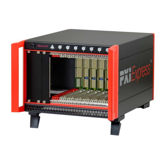
Page 8: System Overview
14579-030 (PXIe System) 2.2 System Overview The 4 U case is based on the Schroff ratiopacPRO-air system with EMC shielding. The 3 U card cage provides 1 system slot (4 - 16 HP) an 7 peripheral slots (4 HP). The lower guide rails of the card cage are equipped with ESD clips. - Page 9 14579-030 (PXIe System) Figure 2: Rear View Power Input Module Fans/Air Outlet Ground stud (M5) Fan Speed Selector Inhibit Mode Selector DSUB-9 Connector, female, Inhibit and volt- age monitoring BNC Connectors 10 MHz REF clock in/out R1.5, April 2021 Product Overview...
-
Page 10: 8 Slot Pxie Backplane (23007-508)
14579-030 (PXIe System) 3 8 Slot PXIe Backplane (23007-508) The PXIe backplane provides: • 1 PXIe system slot • 7 PXI Express Hybrid slots - accepting CompactPCI, PXI, CompactPCI Express, and PXIe modules. • 1 PCIe-to-PCI bridge - utilizes a single PCI segment for the hybrid slots - designed to the PCI Express-to-PCI Bridge Specification 1.0 that enables applications to... -
Page 11: Backplane Topology
14579-030 (PXIe System) 3.1 Backplane Topology Figure 3: Backplane Topology R1.5, April 2021 8 Slot PXIe Backplane (23007-508) -
Page 12: Pcie-To-Pci Bridge
14579-030 (PXIe System) 3.2 PCIe-to-PCI bridge The Schroff PCIe-to-PCI Bridge is a high performance bridge designed to the PCI Express-to- PCI Bridge Specification 1.0 that enables applications to migrate legacy parallel PCI bus interfaces to the advanced serial PCI Express.... -
Page 13: System Synchronisation Clocks
14579-030 (PXIe System) 3.4 System Synchronisation Clocks Acc. to the PXI specifications, the Schroff PXIe system routes the PXI_CLK10 to slot 1-8 and PXIe_CLK100 and PXIe_SYNC100 to the peripheral slots 2-8. PXI_CLK10 is also routed to the external BNC connector 10 MHz REF OUT at the chassis rear side. -
Page 14: Clock Specifications
14579-030 (PXIe System) 3.4.1 Clock specifications For all specifications not mentioned in the tables below refer to the PXI-1 und PXI-5 PXIe Hardware specifications PXI_CLK10 Maximum slot to slot time skew 500 ps Note: PXI-5 spec specifies 1 ns ±25 ppm max (guaranteed over the operating temperature range) ... -
Page 15: Schroff Pxie Chassis Management Module (Cmm)
14579-030 (PXIe System) 3.5 Schroff PXIe Chassis Management Module (CMM) CMM module Backplane voltages I2C interface (5 V aux, 5 V, 3,3 V, +12 V,-12 V) (to SMB on backplane pins XP3 -a3, -b3) Temperature Sensors (4x) Default I2C address 0x58h Select “PS_ON”... -
Page 16: Chassis Status Led
14579-030 (PXIe System) 3.5.1 Chassis status LED The power switch on the front of the chassis has two LEDs (red and white). The table below shows the chassis states and corresponding LED behavior. Chassis state Notification LED behavior Chassis is off... -
Page 17: Power Supply
14579-030 (PXIe System) 3.6 Power Supply Hazardous voltage! Parts of the power supply may be exposed with hazardous voltage. Always remove mains/ line connector before carry out any assembly work. Caution! Your system has not been provided with a AC power cable. Purchase an AC power cable that is approved for use in your country. -
Page 18: Per Slot Power
14579-030 (PXIe System) 3.6.1 Per slot power The table below shows the maximum available electrical power per slot. Please note: • All current carrying backplane pins must be used by the boards • The average cooling capacity of the PXIe chassis is 50 W per slot •... -
Page 19: Power-On Behaviour
14579-030 (PXIe System) 3.7 Power-on behaviour FAN SPEED 1 GND 2 +5 V 3 not used AUTO 4 +3.3 V 5 Inhibit 6 +12 V INHIBIT MODE 7 not used 8 -12 V 9 GND The power-on behaviour depends on the setting of the inhibit mode switch at the rear panel. -
Page 20: Cooling
14579-030 (PXIe System) 4 Cooling The PXIe boards and the power supply are cooled by forced air convection through two 12 VDC axial fans (258 m³/h (172 cfm)). Caution! To maintain proper airflow, all open slots must be covered with filler panels. The filler panel should include an airflow baffle that extends to backplane. -
Page 21: Temperature Settings
14579-030 (PXIe System) 4.1 Temperature Settings 1 NTC temperature sensor is located in top of the card cage and one behind. They are connected to the CMM. The highest temperature level is the reference for the fan speed. To ensure proper fan control, place the PXIe Module with the highest heat dissipation in the slots directly underneath the NTC temperature sensor. -
Page 22: System Controller
14579-030 (PXIe System) 5 System Controller The SCHROFF PXIe system is designed to operate in conjunction with the SCHROFF embedded controller. For the SCHROFF embedded Controller, the chassis INI file and PXIe Chassis dll which come with the system, have to be saved in system directories specified by the instrument and measure management software and system registry settings. -
Page 23: Fan Speed Settings
14579-030 (PXIe System) 5.1 Fan Speed settings Fan Speed and Trigger Bridge settings are managed by the CMM. To access these settings you need access to the resp. CMM register via the system I²C bus (SMB). With the SCHROFF embedded controller, the Fan Speed and Trigger Bridge settings of a SCHROFF PXIe system can be displayed and managed by a dedicated tool called the ... -
Page 24: General Installation Guidelines
14579-030 (PXIe System) 5.2 General Installation Guidelines 5.2.1 Unpacking Caution! When opening the shipping carton, use caution to avoid damaging the system. Consider the following when unpacking and storing the system: • Leave the system packed until it is needed for immediate installation. -
Page 25: Service
14579-030 (PXIe System) 6 Service 6.1 Technical support and Return for Service Assistance We generally recommend to return the complete system. For all product returns and support issues, please contact your Schroff sales distributor. We recommend that you save the packing material. Shipping without the original packing material might void the warranty. -
Page 26: Scope Of Delivery (24579-634)
14579-030 (PXIe System) 6.2 Scope of Delivery (24579-634) Quantity Description ratiopacPRO-air case 4 U / 44 HP, shielded, powder coated (RAL9006/RAL7016) PXIe backplane 8 slot 3 U 600 W power supply with input range of 100 VAC to 240 VAC... -
Page 27: Technical Data
14579-030 (PXIe System) 7 Technical Data Table 2: Technical Data R1.5, April 2021 Technical Data 23... -
Page 28: Dimensions
14579-030 (PXIe System) Dimensions Dimensions Height (w/o feet) 177 mm (4 U) Height (with feet) 192 mm (4 U) Width (with handles) 44 HP (258,7 mm) Depth (Overall with handles) 406.5 mm Weight Completely assembled approx. 5 kg Power Supply... - Page 29 14579-030 (PXIe System) R1.5, April 2021 3Dimensions 25...
- Page 30 14579-030 (PXIe System) 3Dimensions R1.5, April 2021...
- Page 32 Schroff GmbH Langenalber Str. 96 - 100 75334 Straubenhardt, Germany +49.7082.794.0 +49.7082.794.200...
Need help?
Do you have a question about the 14579-030 and is the answer not in the manual?
Questions and answers