Aprilaire 8710 Safety & Installation Instructions
Hide thumbs
Also See for 8710:
- Owner's manual (7 pages) ,
- Safety & installation instructions (11 pages)
Table of Contents
Advertisement
Quick Links
Model 8710
R
Wireless Thermostat
Safety & Installation Instructions
R
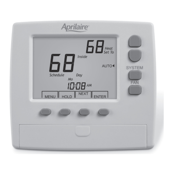
WIRELESS THERMOSTAT
Heat
CONTROL MODULE
Set To
MODEL 8710
Inside
SYSTEM
HEAT
READ AND SAVE
Hold
Mo
AM
THESE INSTRUCTIONS
NEXT
ENTER
MENU
MODE
SOLID RED=HEAT1
FLASHING RED=HEAT2
SOLID YELLOW=COOL1
SOLID GREEN=FAN
FLASHING GREEN=NO CALLS
FLASHING GREEN & RED=NO SIGNAL
Advertisement
Table of Contents

Related Manuals for Aprilaire 8710


Summary of Contents for Aprilaire 8710
- Page 1 Model 8710 Wireless Thermostat Safety & Installation Instructions WIRELESS THERMOSTAT Heat CONTROL MODULE Set To MODEL 8710 Inside SYSTEM HEAT READ AND SAVE Hold THESE INSTRUCTIONS NEXT ENTER MENU MODE SOLID RED=HEAT1 FLASHING RED=HEAT2 SOLID YELLOW=COOL1 SOLID GREEN=FAN FLASHING GREEN=NO CALLS...
-
Page 2: Table Of Contents
TABLE OF CONTENTS Application ..............Selecting Equipment Type ...................... Fan Operation ........... Features ............. Minimum Off Time ..........Specifications Minimum Run Time ........... Control Module Installation ............Heating Setpoint Limit ........Wiring ..............Cooling Setpoint Limit ........Location ............... Heat / Cool Setpoint Temperature ..... -
Page 3: Application
APPLICATION SPECIFICATIONS The Model 8710 is a 7-day programmable, battery Compatible Single stage, multi-stage and heat powered thermostat that communicates via an RF Equipment pumps (3 heat / 2 cool) wireless data link to a control module located near the HVAC equipment. -
Page 4: Control Module
CONTROL MODULE 2.65” .187” DIA. INSTALLATION 2 PLCS. The control module should be installed close to the equipment being controlled. Do not install it within a metal enclosure that might interfere with wireless communications. Only standard 18 gauge thermostat wire is required to wire the module to the equipment. Two #6 sheet metal mounting screws are included or the 5.09”... -
Page 5: Wiring
WIRING - GAS / ELECTRIC (UP TO 2 HEAT / 2 COOL) GAS / ELECTRIC HVAC SYSTEM W2/E W1/B WIRING - HEAT PUMP (UP TO 3 HEAT / 2 COOL) HEAT PUMP SYSTEM W2/E W2/E W1/B... -
Page 6: Location
THERMOSTAT LOCATION The thermostat should be located in an area that represents the ambient space temperature and within 100 feet of the control module. Do not install the thermostat in an area where drafts are present, near the floor, behind doors or on an external wall. Avoid placing the thermostat in areas where the air movement is limited, affected by direct sunlight or other areas not typical of the temperature in the space. -
Page 7: Installing The Sub-Base
INSTALLING THE SUB-BASE INSTALLING BATTERIES The thermostat should be installed approximately 5 feet Slide the battery cover off and install two AA batteries above the floor. included with the thermostat. Install the batteries with the positive terminals to the right as shown. Replace the battery cover. -
Page 8: Thermostat Installer Options
THERMOSTAT INSTALLER OPTIONS Anytime the Zone and/or the Home number is changed The thermostat and control module are factory set to in the thermostat, LINK blinks on the display indicating Zone = 01 Home = 01 and are linked. After the first that the thermostat needs to be linked with a control communication (an equipment call), the thermostat will module. - Page 9 INSTALLER OPTIONS CHART Option Description Option Description Zone number Minimum allowable cooling setpoint Range 1 to 8 Range 55 to 80F Default Default Home number Heat/Cool Setpoint Differential Range 1 to 32 Range 2 to 6F Default Default Stage 1 Temperature Differential Program Control Module with Zone Range 1 to 4F...
-
Page 10: Setting The Zone Number
SETTING THE ZONE NUMBER SETTING THE HOME NUMBER Skip this option if using default setting Zone 01 by Skip this option if using the default setting Home 01 by pressing the NEXT key.. by pressing the NEXT key. 1. Press and hold the ENTER key for seven seconds to Home... -
Page 11: Programming The Control Module
PROGRAMMING THE CONTROL MODULE This option Links the thermostat to a control module. Zone If the thermostat does not need to be linked to a module, skip this option by pressing the NEXT CANCEL key. 1. Press the ENTER key to Link . The thermostat returns to the Home screen. -
Page 12: Selecting Equipment Type
SELECTING EQUIPMENT TYPE FAN OPERATION The control module can be set for either gas/electric or Press the NEXT key to select Option 05 . The fan can heat pump operation. Press the NEXT key to select be set to GA = Gas operation where the equipment Option 04 and press the Down... -
Page 13: Minimum Off Time
MINIMUM OFF TIME MINIMUM RUN TIME The minimum Off time prevents the compressor from The Minimum Run Time influences the cycling rate and restarting too quickly. Large HVAC systems should use a helps to evaporate condensation in heat exchangers. longer Off time. The minimum Off time and the minimum Run time also influence the cycling rate. -
Page 14: Heating Setpoint Limit
HEATING SETPOINT LIMIT COOLING SETPOINT LIMIT The maximum heating setpoint the user can set is 60 to The maximum cooling setpoint the user can set is 55 to 85F. 80F. Press the NEXT key to select Option 08 and press the Press the NEXT key to select... -
Page 15: Heat / Cool Setpoint Temperature
HEAT / COOL SETPOINT DIFFERENTIAL FIRST STAGE DIFFERENTIAL The Heat/Cool temperature differential prevents the First stage temperature differential determines the heating setpoint from being set above or too close to sensitivity of the thermostat. A lower differential will the cooling setpoint, resulting in inadvertent cycling cause the thermostat to cycle more often with smaller between heating and cooling. -
Page 16: Second Stage Differential
SECOND STAGE DIFFERENTIAL THIRD STAGE DIFFERENTIAL Second stage temperature differential determines when the Third stage temperature differential determines when equipment advances from first to second stage. If the the equipment advances from second to third stage. temperature differential between indoor temperature and Setting the differential temperatures the same for setpoint exceeds the second stage temperature differential, second stage and third stage turns second and third... -
Page 17: Timed Upstaging
TIMED UPSTAGING - ON or OFF UPSTAGING TIME Timed Upstaging will turn on the next stage even though If Timed Upstaging is turned on, Option 15 is used to set the temperature differential has not been reached. the stage timing. Press the NEXT key to select... -
Page 18: Calibrating The Temperature Sensor
CALIBRATING THE TEMPERATURE TROUBLESHOOTING THERMOSTAT SENSOR OFFSET AND CONTROL MODULE LINKING Typically, it is not necessary to adjust the temperature Need to terminate control module linking calibration offset from the factory setting. If calibration is The control module blinks red/yellow when waiting to be necessary, a high quality electronic digital thermometer linked with a thermostat. - Page 19 Due to ongoing product improvements, Research Products Corporation reserves the right to change the specifications of the Model 8710 wireless thermostat or its components without notice.
- Page 20 P.O. Box 1467 Madison, WI 53700-1467 Phone 800/334-6011 Fax 608/257-4357 www.aprilairepartners.com 61000828 2011 Aprilaire - A division of Research Products Corporation B2205616C 6.17...
Need help?
Do you have a question about the 8710 and is the answer not in the manual?
Questions and answers