Table of Contents
Advertisement
Quick Links
Advertisement
Table of Contents

Subscribe to Our Youtube Channel
Related Manuals for Waves EMO D5


Summary of Contents for Waves EMO D5
- Page 1 user guide...
-
Page 2: Table Of Contents
Table of Contents Contents Chapter 1: Introduction ..................................3 ......................................1.1 Welcome Overview 1.2 Product ....................................3 Components ......................................4 Chapter 2: Quick Start Guide ................................5 Chapter 3: Interface and Controls .................................. 6 3.1 Interface ......................................6 3.2 Gate Section ....................................7 Compressor Section....................................11 3.4 Leveler Section .................................. -
Page 3: Chapter 1: Introduction
Chapter 1: introduCtion 1. 1 Welcome Thank you for choosing Waves! In order to get the most out of your new Waves plugin, please take a moment to read this user guide. To install software and manage your licenses, you need to have a free Waves account. Sign up at www.waves.com. With a Waves account you can keep track of your products, renew your Waves Update Plan, participate in bonus programs, and keep up to date with important information. -
Page 4: Components
1.3 Components WaveShell technology enables us to split Waves processors into smaller plugins, which we call components. Having a choice of com- ponents for a particular processor gives you the flexibility to choose the configuration best suited to your material. -
Page 5: Chapter 2: Quick Start Guide
As with all Waves plugins, factory presets are a good place to start. Click the Presets button on the WaveSystem toolbar, and choose the preset closest to the source audio you are working with. Tweak it from there. -
Page 6: Chapter 3: Interface And Controls
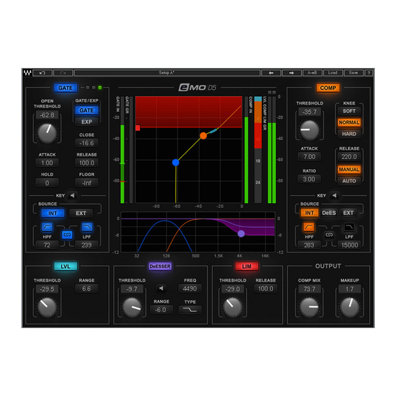
Chapter 3: interfaCe and Controls 3. 1 Interface WaveSystem Toolbar Gate Compressor Leveler DeEsser Limiter Output Filter Graph Input/Output Graph Combined Gain Reduction Meter... -
Page 7: Gate Section
3.2 Gate Section Controls GATE: Turns on or bypasses the Gate section. Range: On, Off Default: Off GATE/EXP: Toggles between Gate and Expander modes. Gate mode provides sharper results, basically muting all audio below the Threshold level. Expander mode provides more natural results, never muting the audio. The Gate is never completely closed, providing “softer”... - Page 8 HOLD: Sets how long the Gate will stay open even if the signal falls below Threshold. Range: 0 to 10000 ms Default: 0 ms RELEASE: Sets how fast the Gate closes (fades out) after the signal falls below Threshold. Range: 1 to 1000 ms Default: 100 ms KEY: Lets you choose, filter and audition the sidechain source.
- Page 9 Meters and Indicators Gate state LEDs Green = Open, Yellow = Hold, Red = Close GATE IN meter Shows input level. When Key is in EXT, the meter will show the input level of the external sidechain. A single red marker on the Gate In meter indicates the Gate Threshold and Close levels.
- Page 10 Input/Output Graph Indicates Gates Range and Open Threshold levels. The Open Threshold level can be adjusted by dragging the blue dot. Gate Key Filters: shown in the Filter Graph as blue curves.
-
Page 11: Compressor Section
3.3 Compressor Section Controls COMP: Turns on or bypasses the Compressor section. Range: On, Off Default: Off KNEE: Sets how aggressively the Compressor reacts to the signal. Range: SOFT, NORMAL, HARD Default: NORMAL THRESHOLD: Sets the Compressor’s engagement level. Range: -48 to 0 db Default: 0 db RATIO: Determines how hard the signal is compressed. - Page 12 KEY: Lets you choose, filter and preview DeEsser and Compressor routing or external sidechain source. The Key feature adds additional precision in controlling dynamics. The Key acts as a trigger that activates the dynamic process. The Key can be internal – triggered by its own signal, or External –...
- Page 13 Meters and Indicators COMP IN Meter: Shows the input level. When Key is in EXT, the meter will show the input level of the External Key. LVL COMP LIM GR Meter: Combined gain reduction meter for the Leveler, Compressor and Limiter. The amount of gain reduction introduced by the Compressor is shown in orange.
- Page 14 Filter Graph: Shows the Compressor's Key filters in orange.
-
Page 15: Leveler Section
3.4 Leveler Section A leveler is used to maintain constant levels over long segments of audio. Essentially, a leveler is a compressor set to very long attack and release times. A leveler can also be viewed as an RMS compressor. The leveler smoothly and transparently gain-rides any signal that exceeds its threshold, bringing it back down as close as possible to the desired target level (the threshold). - Page 16 Meters and Indicators Input/Output Graph: Shows the Leveler’s range and threshold/target levels. Leveler shown as a light blue line. LVL COMP LIM GR Meter: Combined gain reduction meter for the Leveler, the Compressor and the Limiter. The amount of gain reduction introduced by the Leveler is shown in light blue.
-
Page 17: Deesser Section
3.5 DeEsser Section Controls DeESSER: Turns on or bypasses the DeEsser section. Range: On, Off Default: Off THRESHOLD: Sets the DeEsser’s engagement level. The DeEsser’s threshold uses adaptive sensing to provide more natural results. Range: -48 to 0 db Default: 0 db TYPE: Sets the band type –... - Page 18 Meters and Indicators Filter Graph: Shows the DeEsser’s type, frequency, range and DS gain reduction in purple. Frequency and range can be adjusted by dragging the purple dot. Note: The DeEsser’s attenuation is not reflected in the Combined Gain Reduction Meter.
-
Page 19: Limiter Section
3.6 Limiter Section Controls LIM: Turns on or bypasses the Limiter section. Range: On, Off Default: Off THRESHOLD: Sets engage level for Limiter. Range: -48 to 0 db Default: 0 db RELEASE: Sets how fast the Limiter reduces the processing after the signal falls below the Threshold. -
Page 20: Other Meters And Controls
3.7 Other Meters and Controls Makeup Gain The Makeup Gain control is used to compensate for the gain reduction introduced by the multiple dynamic tools. Make sure you don't clip the Output meter when boosting Makeup Gain. Range: -18 to 18 db Default: 0 db Combined Gain Reduction Meter Output Meter... -
Page 21: Emo-D5 Block Diagram
3.8 eMo-D5 Block Diagram...
Need help?
Do you have a question about the EMO D5 and is the answer not in the manual?
Questions and answers