Table of Contents
Advertisement
Quick Links
Advertisement
Table of Contents

Related Manuals for Brandywine FDU-240


Summary of Contents for Brandywine FDU-240
- Page 1 User Guide Frequency Distribution Amplifier Model FDU-240 P/N 022000001 Revision C March 2006 Brandywine Communications 1153 Warner Avenue Tustin, CA 92780 (714) 755 1050 (714) 755 0175 http://www.brandywinecomm.com/ MANUAL P/N 900000035 REV C...
- Page 2 Revision History REVISION DATE COMMENTS 07-14-2004 Original release of FDU-240 user guide. 09-08-2004 Revision of entire FDU-240 user guide. 02-21-2006 Customer’s comments incorporated into FDU-240 user guide. 03-21-2006 Added customer feedback page. MANUAL P/N 900000035 REV C...
- Page 3 Safety Warnings WARNING: This unit contains lethal AC voltages. Disconnect the unit from the AC supply before removing the cover. WARNING: The lightning flash with an arrowhead inside of an equilateral triangle is intended to alert the user to the presence of un-insulated “dangerous voltage”...
-
Page 4: Table Of Contents
Installation ........................9 Connections ....................... 10 3.3.1 Alarm Input Connection ..................10 Operation ..........................11 Powering the FDU-240 ....................11 Selecting the Input Reference..................11 Fault Indicator ......................11 Maintenance and Troubleshooting ..................12 Calibration ..........................13 Drawings ..........................14... -
Page 5: Specifications
Specifications Inputs 1.1.1 Reference Frequency Input • Frequency: 10 MHz ± 0.5 ppm • Amplitude : 0.5 V – 1 Vrms and nominal 1 Vrms factory set • Input Impedance: 50 ohm • Number of Inputs: 2 with auto selection and manual override from the front panel toggle switch •... -
Page 6: Outputs
Outputs 1.2.1 Reference Frequency Output • Number of Outputs: 24 • Connector Type: BNC • Output Protection: short circuit proof • Frequencies Available (same as input): o 10 MHz o 5 MHz • Output Level: +13 ± 2 dBm standard and specified at time of order •... -
Page 7: Switches And Indicators
Switches and Indicators 1.3.1 Status LED Indicators • Power (Green) • Reference Input A Available (Green) • Reference Input A Online (Green) • Reference Input B Available (Green) • Reference Input B Online (Green) • Automatic Reference Selection Selected (Green) •... -
Page 8: Option Configuration Sheet
Option Configuration Sheet FDU-240 CONFIGURATION SHEET PART NUMBER 022000001 CONNECTOR FUNCTION LEVEL INSTALLED ALARM INPUT PIN 1 STATUS A ACTIVE H__L PIN 2 STATUS B ACTIVE H__L PIN 3 NO CONN PIN 4 NO CONN PIN 5 NO CONN PIN 6... -
Page 9: Unpacking And Installation
• 1 power cord • 1 user guide Note the power entry module on the rear of the FDU-240 chassis. Please take note of the voltage displayed on the rear of the power entry module and verify that the voltage matches the local line’s voltage. -
Page 10: Connections
GOOD. A built in pull-up resistor ensures that if no ALARM IN connection is made the reference is considered good. To change the polarity of the ALARM IN, remove the top cover of the FDU-240 and set the links to the link settings seen in the table below. -
Page 11: Operation
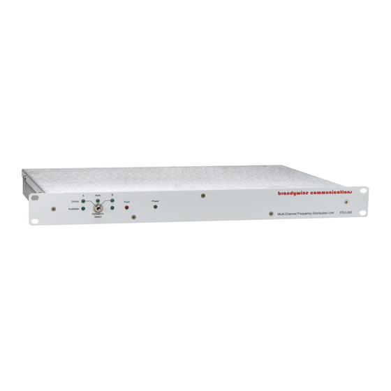
Refer to Figure 1 for a guide of the front panel controls and indicators. Powering the FDU-240 Once all connections to the FDU-240 have been made, apply power to the unit by placing the on/off switch to the on position. The on/off switch is located on the rear panel power entry module. -
Page 12: Maintenance And Troubleshooting
Maintenance and Troubleshooting There is no preventive maintenance required for the FDU-240. SYMPTOM POTENTIAL CAUSE CORRECTIVE ACTION No signal 1. There is no input 1. Connect the reference outputs reference. input. 2. The Reference Select 2. Select an internal source. -
Page 13: Calibration
The frequency counter MUST be configured to use an external reference such as a Cesium, Rubidium, or GPS disciplined OCXO as its time-base. The calibration accuracy of the FDU-240 can only be as accurate as the reference against which it is calibrated. It should be better than 1x10 5. -
Page 14: Drawings
Drawings FIGURE DESCRIPTION FDU-240 Front Panel FDU-240 Rear Panel FDU-240 Mechanical Outline FDU-240 Link Location MANUAL P/N 900000035 REV C... - Page 19 714 755 1050 Tel 714 755 0175 Fax Please take a moment to help us improve your experience with Brandywine Communications. When you’re done, please either email this form to lisap@brandywinecomm.com or fax this form to 714 755 0175. PRODUCT QUALITY...
Need help?
Do you have a question about the FDU-240 and is the answer not in the manual?
Questions and answers