Table of Contents
Advertisement
Quick Links
Advertisement
Table of Contents

Related Manuals for Brandywine FTSU-100D


Summary of Contents for Brandywine FTSU-100D
- Page 1 User Guide Frequency and Time Synthesizer Unit Model FTSU-100D P/N 001-0187 Revision A March 2010 Brandywine Communications 1153 Warner Ave. Tustin, CA 92780 (714) 755 1050 (714) 755 0175 http://www.brandywinecomm.com MANUAL P/N 900000106 REV A...
- Page 2 Revision History REVISION DATE COMMENTS 03-29-2010 Initial Release MANUAL P/N 900000106 REV A...
- Page 3 Safety Warnings WARNING: This unit contains lethal AC voltages. Disconnect the unit from the AC supply before removing the cover. WARNING: The lightning flash with an arrowhead inside of an equilateral triangle is intended to alert the user to the presence of un-insulated “dangerous voltage” within the product’s enclosure.
- Page 4 This page intentionally left blank MANUAL P/N 900000106 REV A...
-
Page 5: Table Of Contents
Installation....................10 Connections..................... 11 3.3.1 Power ....................11 3.3.2 Other Connections................. 11 Getting Started ....................12 Powering Up the FTSU-100D............... 12 Setting the Network Address................ 12 4.2.1 IPSetup.exe ..................13 4.2.2 Web Browser..................14 Latest Version of Java Software ..............15 Configuration.................... -
Page 6: Specifications
1 Specifications Inputs 1.1.1 1 PPS Input Rate: 1 Hz Amplitude: 2,5V – 10V Termination: 50 ohm (menu selectable) Number of Inputs: 2 with auto selection and manual override. 1.1.2 10MHz Input Frequency: 10 MHz Amplitude: 0.5 V – 1 Vrms. Input Impedance: 50 ohm Outputs... -
Page 7: Network Port
17” x 1.72” x 9” excluding the connectors and handles. Front panel width 19”. Weight 5 lbs. nominal Rack mount slides General Devices P/N C300-S-116 Brandywine P/N 002000105 General Devices P/N C300-S-124 Brandywine P/N 002000123 MANUAL P/N 900000106 REV A... -
Page 8: Rear Panel Connections
Rear Panel Connections CONNECTOR REFERENCE CONNECTOR CONNECTOR SIGNAL TYPE J1 , J2, J3, J4, J5, J6, J7, J8 CENTER 10 MHz Outputs SHIELD J9, J10, J11, J12, J13, J14, J15, J16 CENTER 70 MHz Outputs SHIELD J17, J18, J19, J20, J21, J22, J23, CENTER 1PPS Outputs SHIELD... -
Page 9: General Description
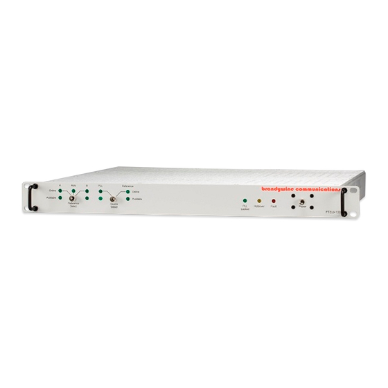
PTS Precision Time System. The FTSU-100D is contained in a compact IU rack-mount chassis. The FTSU accepts two sets of inputs. An input set comprises a 10 MHz reference frequency, a 1PPS signal and status inputs from the reference generator. The FTSU- 100D provides automatic changeover should one of the source inputs fail. -
Page 10: Unpacking And Installation
• 1 user guide Note the power entry module on the rear of the FTSU-100D chassis. Please take note of the voltage displayed on the rear of the power entry module and verify that the voltage matches the local line’s voltage. -
Page 11: Connections
If the rack mount slides (P/N 002000105) are used they must be attached to the FTSU-100D chassis with 10/32 screws. CAUTION: DO NOT USE SECURING SCREWS LONGER THAN 0.5” BECAUSE THIS MAY RESULT IN INTERNAL DAMAGE TO THE FTSU-100D. Connections 3.3.1... -
Page 12: Getting Started
Fault LEDs should be extinguished. The FTSU-100D is now ready for operation. Setting the Network Address The FTSU-100D is shipped with a label that indicates the IP address stored in the unit. The default settings are: • IP Address: 192.168.1.160 •... -
Page 13: Ipsetup.exe
To transfer the settings to the selected FTSU-100D unit, click the button. Wait 15 seconds for the settings to be loaded into the FTSU-100D unit and for the FTSU-100D unit to restart. Verify that the FTSU-100D unit has the correct network settings and is connected to the network by clicking the Search Again button. -
Page 14: Web Browser
Connect one end of an Ethernet cable to the FTSU-100D Network Port. Connect the other end of the Ethernet cable to your network. Open a web browser, type the IP Address of the FTSU-100D unit in the Address bar, and press <Enter>. For example, type 192.168.1.1 or http://192.168.1.1... -
Page 15: Latest Version Of Java Software
Latest Version of Java Software To properly control and monitor the FTSU-100D via a web browser based interface, Java software must be installed on your computer. To obtain the Java software, follow the steps given below. Go to http://www.sun.com/ Click on the Downloads link. -
Page 16: Configuration
The System Status section consists of ten fields, the Version, Reference Select, Source Select, Fault, Input A Status, Input B Status, Channel A 10MHz, Channel B 10MHz, Channel A 50 ohm and Channel B 50 ohm. The Version refers to the firmware version number of the FTSU-100D. MANUAL P/N 900000106 REV A... -
Page 17: Setup
The System section consists of two fields, the Version and Unit Location. The Version refers to the version number of the FTSU-100D software. The Unit Location refers to the location of the unit on your network. A maximum of 127 characters may be entered in the Unit Location field. Entering apostrophes (‘) in the Unit Location field is not recommended. - Page 18 Please note that once the IP address is changed using the web browser, the user must enter the new IP address in the address bar of the web browser to continue monitoring the FTSU-100D. If an IP address is entered that is not reachable from the computer running the web browser, it will not be possible to reconnect to the FTSU-100D via the web browser based interface.
-
Page 19: Password
Password screen, click the Submit button. To undo all modifications made to the Password screen, click the Reset button. IMPORTANT INFORMATION: The default user name and password for the system is BRANDYWINE. The user must always enter a user name and password when submitting changes to the system. Figure 5 Password Screen The Password consists of four fields, the New User Name, Old Password, New Password, and Confirm New Password. -
Page 20: Alarm
5.1.4 Alarm The Alarm tab consists of the Index and the Fault Detected sections. Figure 6 Alarm Screen MANUAL P/N 900000106 REV A... -
Page 21: Pps
5.1.5 1 PPS The 1 PPS tab consists of three sections, the 1PPS Output Width, 1PPS Delay and 50 ohm Load. Figure 7 1PPS MANUAL P/N 900000106 REV A... - Page 22 5.1.5.1 1 PPS Output Width The 1 PPS output pulse width can be set by entering the value directly into the box. The range of acceptable values is 100 ns to 6 500 000 ns. 5.1.5.2 1 PPS Delay Each 1 PPS output can be delayed or advanced by as much as ½ a second. To delay an output, enter “...
-
Page 23: Output
5.1.6 Output The Output tab consists of the Output Setup for the 10MHz and 70MHz outputs. To save all modifications made to each output, click the button. Figure 8 Output Each high frequency output has three adjustable settings, and displays the actual output amplitude of that signal. -
Page 24: Serial
The third box, labeled “ Output Setting “, allows the user to adjust the signal output amplitude. The effective range is 0 to 3,000 Volts. The “ Actual “ column displays the actual value of the output signal. Note that output signal loading and termination will affect the actual readings. -
Page 25: Snmp
The Simple Network Management Protocol (SNMP) is a protocol used to expose variables to a Network Management System (NMS). The variables are arranged in a Management Information Base (MIB). The Brandywine Communications FTSU-100D SNMP version 1 includes MIB-II and the capabilities listed below. - Page 26 Once the community names are entered, they are stored in non-volatile memory and will be recalled when the FTSU-100D is powered up. describes the read/write commands used by SNMP.
-
Page 27: Help
5.1.9 Help The Help tab provides the user with help while using difficult areas in the system. Help links are located throughout the entire system so the user has access to the Help screen whenever the user encounters a problem. Once the user clicks on the Help link the user will be automatically redirected to the Help screen. Various topics are discussed in the Help screen. -
Page 28: Uploading Firmware
Figure 12 Figure 12 AutoUpdate Screen 2. Enter the IP address of the FTSU-100D in the IP address field. If the user does not know the IP address, press the Find button and will be displayed. Locate and click on the IP address Figure 13 of the unit and click the OK button. - Page 29 3. Enter the path name to the new released file. If the user does not know the path name, press the Browse button and will be displayed. Locate and click on the file and click the Open Figure 14 button. The File Name field will be completed for you. Figure 14 Open Screen 4.
- Page 30 Figure 16 AutoUpdate Complete Screen MANUAL P/N 900000106 REV A...
-
Page 31: Maintenance And Troubleshooting
Maintenance and Troubleshooting There is no required preventive maintenance for the FTSU-100D. To troubleshoot the problems, refer to Table 4 SYMPTOM POTENTIAL CAUSE CORRECTIVE ACTION No LEDs 1. There is no power. 1. Verify that the AC power is available. -
Page 32: Drawings
Drawings FIGURE DESCRIPTION FTSU-100D Front Panel FTSU-100D Rear Panel Table 21 FTSU-100D Drawings MANUAL P/N 900000106 REV A... - Page 33 Figure 1 FTSU-100D Front Panel Figure 2 FTSU-100D Rear Panel MANUAL P/N 900000106 REV A...
Need help?
Do you have a question about the FTSU-100D and is the answer not in the manual?
Questions and answers