Table of Contents

Related Manuals for Brandywine IBU-240


Summary of Contents for Brandywine IBU-240
- Page 1 User Guide IRIG Distribution Amplifier Model IBU-240 P/N 019000001 Revision A February 2006 Brandywine Communications 1153 Warner Avenue Tustin, CA 92780 (714) 755 1050 (714) 755 0175 http://www.brandywinecomm.com MANUAL P/N 900000025 REV A...
- Page 2 Revision History REVISION DATE COMMENT 08-31-04 Original release of IBU-240 user guide. 02-20-06 Section 1.1.3 Fault/Status added. MANUAL P/N 900000025 REV A...
- Page 3 Safety Warnings WARNING: This unit contains lethal AC voltages. Disconnect the unit from the AC supply before removing the cover. WARNING: The lightning flash with an arrowhead inside of an equilateral triangle is intended to alert the user to the presence of un-insulated “dangerous voltage”...
-
Page 4: Table Of Contents
Installation......................9 Connections......................9 3.3.1 Alarm Input Connection ..................10 Operation ..........................11 Powering the IBU-240 ..................11 Selecting the Input Reference ................11 Fault Indicator ...................... 12 Maintenance and Troubleshooting ..................13 Diagrams..........................14 MANUAL P/N 900000025 REV A... -
Page 5: Specifications
Specifications Inputs 1.1.1 Time Code Input • Frequency: 300 Hz – 50 KHz • Amplitude : 4 V • Input Impedance: 600 ohm • Number of Inputs: 2 with auto selection and manual override from the front panel toggle switch •... -
Page 6: Switches And Indicators
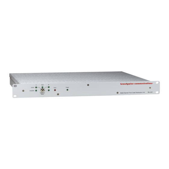
Switches and Indicators 1.3.1 Status LED Indicators • Power (Green) • Reference Input A Available (Green) • Reference Input A Online (Green) • Reference Input B Available (Green) • Reference Input B Online (Green) • Automatic Reference Selection Selected (Green) •... -
Page 7: Option Configuration Sheet
Option Configuration Sheet IBU-240 CONFIGURATION SHEET PART NUMBER 019000001 CONNECTOR FUNCTION LEVEL INSTALLED ALARM INPUT PIN 1 STATUS A ACTIVE H__L PIN 2 STATUS B ACTIVE H__L PIN 3 NO CONN PIN 4 NO CONN PIN 5 NO CONN PIN 6... -
Page 8: Unpacking And Installation
• 1 power cord • 1 user guide Note the power entry module on the rear of the IBU-240 chassis. Please take note of the voltage displayed on the rear of the power entry module and verify that the voltage matches the local line’s voltage. -
Page 9: Installation
Installation The IBU-240 should be bolted directly into a 19” rack mount enclosure or mounted on a shelf. The IBU-240 when fully populated has up to 27 cables attached to the rear panel, therefore it is recommended that some appropriate cable strain-relief system be used to support these cables, particularly when the IBU-240 is not mounted on a shelf. -
Page 10: Alarm Input Connection
ALARM IN connection is made, the reference is still considered good. To change the polarity of the ALARM IN, remove the top cover of the IBU-240 and set the links to the link settings seen in the tables shown below. -
Page 11: Operation
Powering the IBU-240 Once all connections to the IBU-240 have been made, apply power to the unit by moving the On/Off switch to the on position. The On/Off switch is located on the rear panel of the power entry module. -
Page 12: Fault Indicator
Fault Indicator The red LED on the front panel indicates that one or more of the outputs have a low signal. The four potential causes for a low signal are listed below: 1. The input signal level is too low therefore the output signal monitors have registered the low level as a fault. -
Page 13: Maintenance And Troubleshooting
Maintenance and Troubleshooting There is no preventive maintenance required for the IBU-240. Moreover, no periodic calibration is required. SYMPTOM POTENTIAL CAUSE CORRECTIVE ACTION No signal 1. There is no input 1. Connect the reference outputs reference. input. 2. The Reference Select 2. -
Page 14: Diagrams
Diagrams FIGURE DESCRIPTION IBU-240 Front Panel IBU-240 Rear Panel IBU-240 Mechanical Outline MANUAL P/N 900000025 REV A...
Need help?
Do you have a question about the IBU-240 and is the answer not in the manual?
Questions and answers