Table of Contents
Advertisement
Quick Links
Advertisement
Table of Contents

Related Manuals for Keysight Technologies M9188A


Summary of Contents for Keysight Technologies M9188A
- Page 1 Keysight M9188A PXI D/A Converter 16-Bit, 0-30 V, 0-20 mA Startup Guide...
- Page 3 M9188A Startup Guide...
- Page 4 Notices Warranty Safety Notices © Keysight Technologies 2014 No part of this manual may be reproduced in The material contained in this docu- any form or by any means (including elec- ment is provided “as is,” and is sub- C A U T I O N...
- Page 5 To prevent electrical tures. The American National Standards Institute (ANSI) states that a shock hazard shock do not remove covers. exists when voltage levels greater than 30 V RMS, 42.4 V peak, or 60 VDC are present. M9188A Startup Guide...
- Page 6 Class A product (CISPR 11, Clause 4). This symbol indicates the time period during which no hazard- ous or toxic substance elements are expected to leak or deterio- rate during normal use. Forty years is the expected useful life of the product. M9188A Startup Guide...
- Page 7 “Monitoring and Control Instrument” product. The affixed product label is as shown below. Do not dispose in domestic household waste. To return this unwanted instrument, contact your nearest Keysight Service Center, or visit www.keysight.com/environment/product for more information. M9188A Startup Guide...
- Page 8 THIS PAGE HAS BEEN INTENTIONALLY LEFT BLANK. M9188A Startup Guide...
-
Page 9: Table Of Contents
Power up the controller 8 Install the softwares 8 Step 4: Install the Module 10 M9188A front panel 14 M9188A system connections 17 Step 5: Verify the Operation of the M9188A Module 18 Conduct performance verification (optional) 20 Specifications 23 M9188A Startup Guide... - Page 10 THIS PAGE HAS BEEN INTENTIONALLY LEFT BLANK. VIII M9188A Startup Guide...
-
Page 11: Introduction
Check the manual revision on the second page of each manual. • Keysight M9188A PXI D/A Converter 16- Bit, 0- 30 V, 0- 20 mA Startup Guide. This manual. Printed copy for outdoor use, included with shipment. -
Page 12: Step 1: Unpack And Inspect The Module
Step 1: Unpack and Inspect the Module Step 1: Unpack and Inspect the Module The M9188A is shipped in materials which prevent damage from static. C A U T I O N The module should only be removed from the packaging in an anti-static area after ensuring that correct anti-static precautions are taken. -
Page 13: Inspect The Module For Damage
Keysight M9188A PXI D/A Converter 16-Bit, 0-30 V, 0-20 mA Step 1: Unpack and Inspect the Module Purchase acceptable ESD accessories from your local supplier. • Conductive table- mat and wrist- strap combination. • Conductive floor- mat and heel- strap combination. -
Page 14: Return The Module For Service
Keysight M9188A PXI D/A Converter 16-Bit, 0-30 V, 0-20 mA Step 1: Unpack and Inspect the Module Return the module for service Should it become necessary to return the M9188A for repair or service, follow the steps below: 1 Review the warranty information shipped with your product. -
Page 15: Step 2: Verify The Shipment Contents
Step 2: Verify the Shipment Contents The following items are included in the M9188A shipment: • M9188A PXI D/A Converter 16- Bit, 0- 30 V, 0- 20 mA Software and Product Information CD- ROM (P/N: M9188- 10001) - contains software, drivers, and all product documentation in PDF format. -
Page 16: Step 3: Install The Software
Keysight M9188A PXI D/A Converter 16-Bit, 0-30 V, 0-20 mA Step 3: Install the Software Step 3: Install the Software System requirements The following table lists the minimum system requirements for Keysight IO Libraries Suite. In general, any x86 or x64 (except Itanium) architecture should work but there may be a significant decrease in performance. - Page 17 Keysight M9188A PXI D/A Converter 16-Bit, 0-30 V, 0-20 mA Step 3: Install the Software Table 1 Minimum system requirements Interface controller A PXI or PXIe remote or embedded controller. Remote controller A Keysight M9045A ExpressCard interface (for portable laptops) or Keysight M9047A PCIe interface (for desktop PCs) or equivalent PXI or PXIe remote controllers running one of the above operating systems.
-
Page 18: Power Up The Controller
Keysight M9188A PXI D/A Converter 16-Bit, 0-30 V, 0-20 mA Step 3: Install the Software Power up the controller If you are using a remote controller, power up the host computer. If you are using an embedded controller, complete the... - Page 19 Keysight M9188A PXI D/A Converter 16-Bit, 0-30 V, 0-20 mA Step 3: Install the Software Figure 2 InstallShield Wizard for Keysight M9188A 3 After installation is complete, power down the chassis (and the host PC if using the remote controller).
-
Page 20: Step 4: Install The Module
• Before installing the M9188A into the chassis, ensure that the chassis is powered off and unplugged to prevent damage to the module. The M9188A module can be used in a chassis with a cPCI, PXI-1, or PXIh N O T E chassis peripheral slot. - Page 21 Keysight M9188A PXI D/A Converter 16-Bit, 0-30 V, 0-20 mA Step 4: Install the Module Figure 3 Installing the module to the chassis 5 Hold the module by the injector/ejector handle, and slide it into an available PXI (or hybrid) slot, as shown in Figure •...
- Page 22 Keysight M9188A PXI D/A Converter 16-Bit, 0-30 V, 0-20 mA Step 4: Install the Module 10 Install all chassis covers and filler panels after installing the module. Missing filler panels may disrupt necessary air circulation in the chassis. 11 If you are using a remote controller, connect the System Interface Card in the chassis to host computer.
- Page 23 Keysight M9188A PXI D/A Converter 16-Bit, 0-30 V, 0-20 mA Step 4: Install the Module Module installation procedures Press down the ejector. Slide the M9188A module into any slot until the backplane connectors touch. Seat the M9188A module into the mainframe by pulling up the ejector.
-
Page 24: M9188A Front Panel
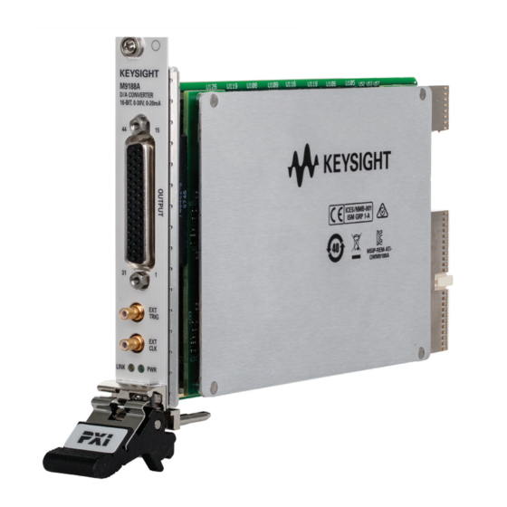
Keysight M9188A PXI D/A Converter 16-Bit, 0-30 V, 0-20 mA Step 4: Install the Module M9188A front panel Figure 5 M9188A PXI D/A converter front panel M9188A Startup Guide... - Page 25 Keysight M9188A PXI D/A Converter 16-Bit, 0-30 V, 0-20 mA Step 4: Install the Module Pin 30 Pin 16 Figure 6 M9188A output connector pinout M9188A Startup Guide...
- Page 26 Keysight M9188A PXI D/A Converter 16-Bit, 0-30 V, 0-20 mA Step 4: Install the Module Table 2 M9188A output DSUB pinout assignment CH1+ CH2+ CH3+ CH1– CH2– CH3– CH4+ CH5+ CH6+ CH4– CH5– CH6– CH7+ CH8+ CH9+ CH7– CH8– CH9–...
-
Page 27: M9188A System Connections
Keysight M9188A PXI D/A Converter 16-Bit, 0-30 V, 0-20 mA Step 4: Install the Module M9188A system connections Figure 7 M9188A functional block diagram M9188A Startup Guide... -
Page 28: Step 5: Verify The Operation Of The M9188A Module
Keysight M9188A PXI D/A Converter 16-Bit, 0-30 V, 0-20 mA Step 5: Verify the Operation of the M9188A Module Step 5: Verify the Operation of the M9188A Module The intention of this step is to verify the basic operations of the newly installed module. - Page 29 Keysight M9188A PXI D/A Converter 16-Bit, 0-30 V, 0-20 mA Step 5: Verify the Operation of the M9188A Module In this example, we will configure the SFP to output DC voltage from Channel 4 the moment we click Output. 1 First, ensure that the 10 MHz Referecence Clock Source and Trigger and Event is set to Internal Clock and Immediate respectively.
-
Page 30: Conduct Performance Verification (Optional)
Output Relay, Single Channel: CH4 button to OFF. This will turn off the signal and disconnect the output relay. You may refer to Keysight M9188A Soft Front Panel Help for details on how to use the SFP. Conduct performance verification (optional) - Page 31 Keysight M9188A PXI D/A Converter 16-Bit, 0-30 V, 0-20 mA Step 5: Verify the Operation of the M9188A Module Table 3 Required functionality verification hardware Hardware Description Keysight 34411A 6.5-Digit Digital Multimeter M9188A voltage mode verification procedure 1 Run the M9188A Soft Front Panel (SFP).
- Page 32 Keysight M9188A PXI D/A Converter 16-Bit, 0-30 V, 0-20 mA Step 5: Verify the Operation of the M9188A Module M9188A current mode verification procedure 1 Run the M9188A Soft Front Panel (SFP). 2 Connect the channel +ve pin to the I input of the ammeter.
-
Page 33: Specifications
If a problem is found, perform the following checks: 1 Verify that all relevant hardware is turned on. 2 Verify that the M9188A paths are correctly set from the SFP and that the multimeter is set to the proper voltage measurement range and that cable is properly connected. - Page 34 Keysight M9188A PXI D/A Converter 16-Bit, 0-30 V, 0-20 mA Step 5: Verify the Operation of the M9188A Module THIS PAGE HAS BEEN INTENTIONALLY LEFT BLANK. M9188A Startup Guide...
- Page 35 Contact us To obtain service, warranty, or technical assis- tance, contact us at the following phone or fax numbers: United States: (tel) 800 829 4444 (fax) 800 829 4433 Canada: (tel) 877 894 4414 (fax) 800 746 4866 China: (tel) 800 810 0189 (fax) 800 820 2816 Europe: (tel) 31 20 547 2111...
- Page 36 This information is subject to change without notice. © Keysight Technologies 2014 Edition 1, August 2014 *M9188-90001* M9188-90001 www.keysight.com...
Need help?
Do you have a question about the M9188A and is the answer not in the manual?
Questions and answers